5. CONFIGURATION
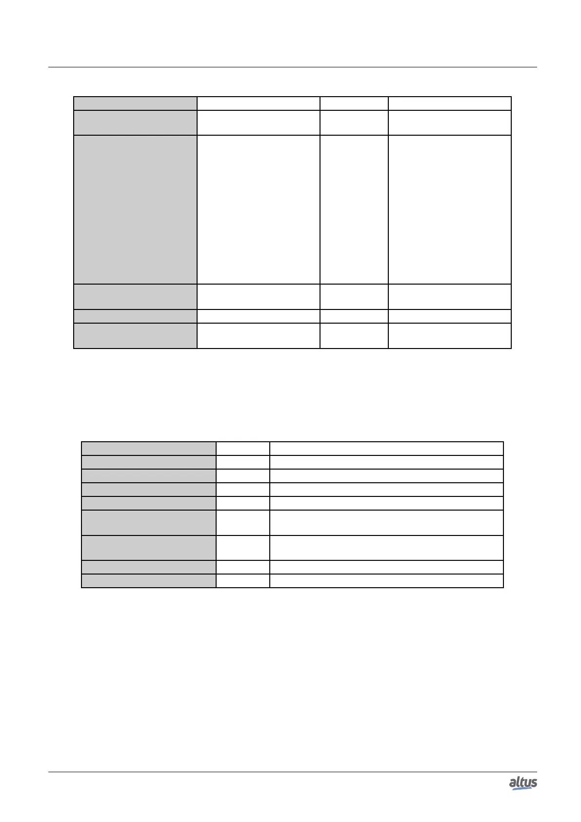
Configuration Description Default Options
Value Variable Symbolic variable name -
Name of a variable declared
in a program or GVL
Data Type MODBUS data type -
Coil - Write (1 bit)
Coil - Read (1 bit)
Holding Register - Write
(16 bits)
Holding Register - Read (16
bits)
Holding Register – Mask
And (16 bits)
Holding Register – Mask
Or (16 bits)
Input Register (16 bits)
Input Status (1 bit)
Data Start Address
Initial address of the MOD-
BUS data
- 1 to 65536
Data Size Size of the MODBUS data - 1 to 65536
Data Range
The address range of config-
ured data
- -
Table 87: MODBUS Mappings Settings
Notes:
Value Variable: this field is used to specify a symbolic variable in MODBUS relation.
Data type: this field is used to specify the data type used in the MODBUS relation.
Data Type Size [bits] Description
Coil - Write 1 Writing digital output.
Coil - Read 1 Reading digital output.
Holding Register - Write 16 Writing analog output.
Holding Register - Read 16 Reading analog output.
Holding Register - Mask And 16
Analog output which can be read or written with AND
mask.
Holding Register - Mask Or 16
Analog output which can be read or written with OR
mask.
Input Register 16 Analog input which can be only read.
Input Status 1 Digital input which can be only read.
Table 88: Data Types Supported in MODBUS
Data Start Address: Data initial address of a MODBUS mapping.
Data Size: The size value specifies the maximum amount of data that a MODBUS interface can access, from the initial
address. Thus, to read a continuous address range, it is necessary that all addresses are declared in a single interface. This field
varies with the MODBUS data type configured.
Data Range: This field shows to the user the memory address range used by the MODBUS interface.
5.5.5.1.4. Requests Configuration – Symbolic Mapping Settings
The configuration of the MODBUS requests, viewed in figure below, follow the parameters described in table below:
109
 Loading...
