2. TECHNICAL DESCRIPTION
2. Technical Description
This chapter presents all technical features from NX3030.
2.1. Panels and Connections
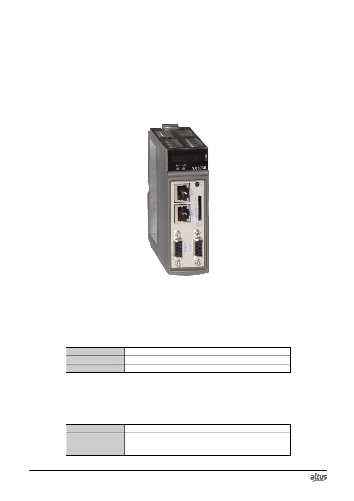
The following figure shows the CPU front panel.
Figure 3: NX3030
As it can be seen on the figure, on the front panel upper part is placed the graphic display used to show the whole system
status and diagnostics, including the specific diagnostics of each module. The graphic display also offers an easy-to-use menu
which brings to the user a quick mode for parameters reading or defining, such as: inner temperature (reading only) and local
time (reading only).
Just below the graphic display, there are 2 LEDs used to indicate alarm diagnostics and watchdog circuit. The table below
shows the LEDs description. For further information regarding the LEDs status and meaning, see Diagnostics via LED section.
LED Description
DG Diagnostics LED
WD Watchdog LED
Table 2: LEDs Description
Nexto Series CPUs has two switches available to the user. The table below shows the description of these switches. For
further information regarding the diagnostics switch, see sections One Touch Diag and CPU’s Informative and Configuration
Menu. For further information regarding the MS switch, see section Memory Card.
Keys Description
Diagnostics Switch
Switch placed on the module upper part. Used for diagnostics vi-
sualization on the graphic display or for navigation through the in-
formative menu and CPU configuration.
6

 Loading...