6. REDUNDANCY WITH NX3030 CPU
ATTENTION
In case of redundant networks, only the parameters of the NX5001 to the far left on the bus
must be adjusted, while the NX5001 at the right remain blocked for edition. Some network
parameters are identical to the other network while others are calculated automatically from
network parameters of the left NX5001.
It’s recommended for the configured address for a NX5001 master in a redundant PLC to be 2, as the master NX5001
address in the Non-Active PLC is decremented one unit, thus the NX5001 master address results 1.
Besides that, it’s important to remember:
The addresses from 3 to 125 are usually used for PROFIBUS slaves
The 0 address is frequently used for device configuration and diagnostics
The address 1 is reserved to be taken, dynamically, by the PROFIBUS master in the Non-Active PLC (PROFIBUS
master in passive mode)
The 126 address is frequently used for slave devices when comes from the manufacturer
The 127 address is used for broadcast frames
In the next project compilation, MasterTool check the possible errors the user may have made at inserting or removing
NX5001 modules manually.
Important to note that during the execution of a project previously configured with redundant NX5001 modules, bit 0
Command (Channel Enable Interface %QXn.0 at Bus I/O Mapping tab) is handled by the redundant application. The interfaces
must remain qualified throughout the program. Thus, a command run by the user to disable an interface will not run the way
it’s expected. For example, if an interface has the status of this bit changed from TRUE to FALSE on an active CPU, this will
not be interpreted as a failure that would take the CPU Active for the Inactive state. In this case, the CPU will remain in Active
and the other CPU that will go to the Inactive state. For these reasons, this command bit should not be manipulated by the user
in a redundant application.
For further information regarding PROFIBUS networks configuration, see PROFIBUS-DP NX5001 Utilization Manual.
6.4.4.3. PROFIBUS Remotes Configuration
To configure PROFIBUS remotes under a NX5001 master, the PROFIBUS-DP NX5001 Master Utilization Manual must
be consulted, together with the following manuals:
Ponto Series Utilization Manual
PROFIBUS PO5063V1 Head and Redundant PROFIBUS PO5063V5 Head Utilization Manual
PROFIBUS PO5064 Head and Redundant PROFIBUS PO5065 Head Utilization Manual
HART over PROFIBUS Network Utilization Manual
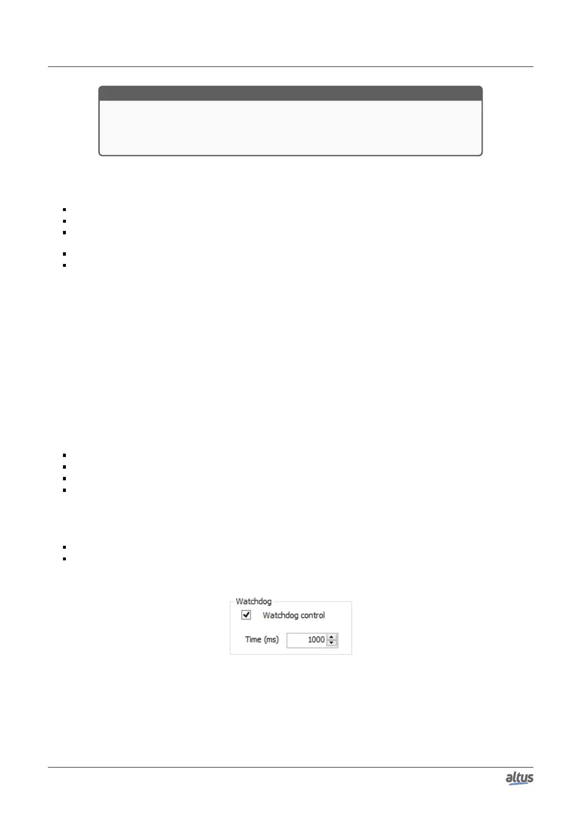
For a redundant system we must pay attention to the configuration of the watchdog parameter from the PROFIBUS remote.
In case that, in the remote configuration screen, the Watchdog control checkbox is checked, the Time field needs to be correctly
configured. There are two options to configure the Time and we must use the bigger time between:
WT ≥ I x 2 + 500ms; and
WT ≥ I x 3;
Where WT is the watchdog time and I is the MainTask configured interval.
Figure 186: Watchdog Configuration of a PROFIBUS Remote
311
 Loading...
