5. CONFIGURATION
Write Mask of IEC Variables: the Mask Write Register function (FC 22) employs a logic between the value already
written and the two words that are configured in this field using %QW(0) for the AND mask and %QW(2) for the OR mask;
allowing the user to handle the word. This field is limited by the size of output variables addressable memory (%Q) of each
CPU, which can be found in the section Memory.
Default Value: the factory default value cannot be set for the Mapping Diagnostics Area, Read IEC Variable, Write IEC
Variable and Mask Write IEC Variables fields, since the creation of a relation can be performed at any time on application
development. The MasterTool IEC XE software itself allocate a value from the range of direct representation output variables
(%Q), still unused. Factory default cannot be set to the Read/Write Data Size fields, as they will vary according to the
MODBUS data type selected.
ATTENTION
Unlike other tasks of an application, when a mark is reached at MainTask debugging, the
MODBUS Ethernet Client instance task or any other MODBUS task will stop being executed
at the moment it tries to write in the memory area. This occurs in order to maintain data
consistency of memory areas while MainTask is not running.
5.5.8.3. MODBUS Client Relation Start in Acyclic Form
To start a MODBUS Client relation in acyclic form, it is suggested the following method which can be implemented in a
simple way in the user application program:
Define the maximum polling time for the relations;
Keep the relation normally disabled;
Enable the relation at the moment the execution is desired;
Wait for the confirmation of the relation execution finishing and, at this moment, disable it again.
5.5.9. MODBUS Ethernet Server
This protocol is available for all Nexto Series CPUs on its Ethernet channels. When selecting this option at MasterTool
IEC XE, the CPU becomes a MODBUS communication server, allowing the connection with MODBUS client devices. This
protocol is only available when the CPU is in execution mode (Run Mode).
There are two ways to configure this protocol. The first one makes use of direct representation (%Q), in which the variables
are defined by your address. The second one, through symbolic mapping, where the variables are defined by your name.
The procedure to insert an instance of the protocol is found in detail in the MasterTool IEC XE User Manual – MU299609.
5.5.9.1. MODBUS Server Ethernet Protocol Configuration for Symbolic Mapping
To configure this protocol using Symbolic Mappings, it is necessary to execute the following steps:
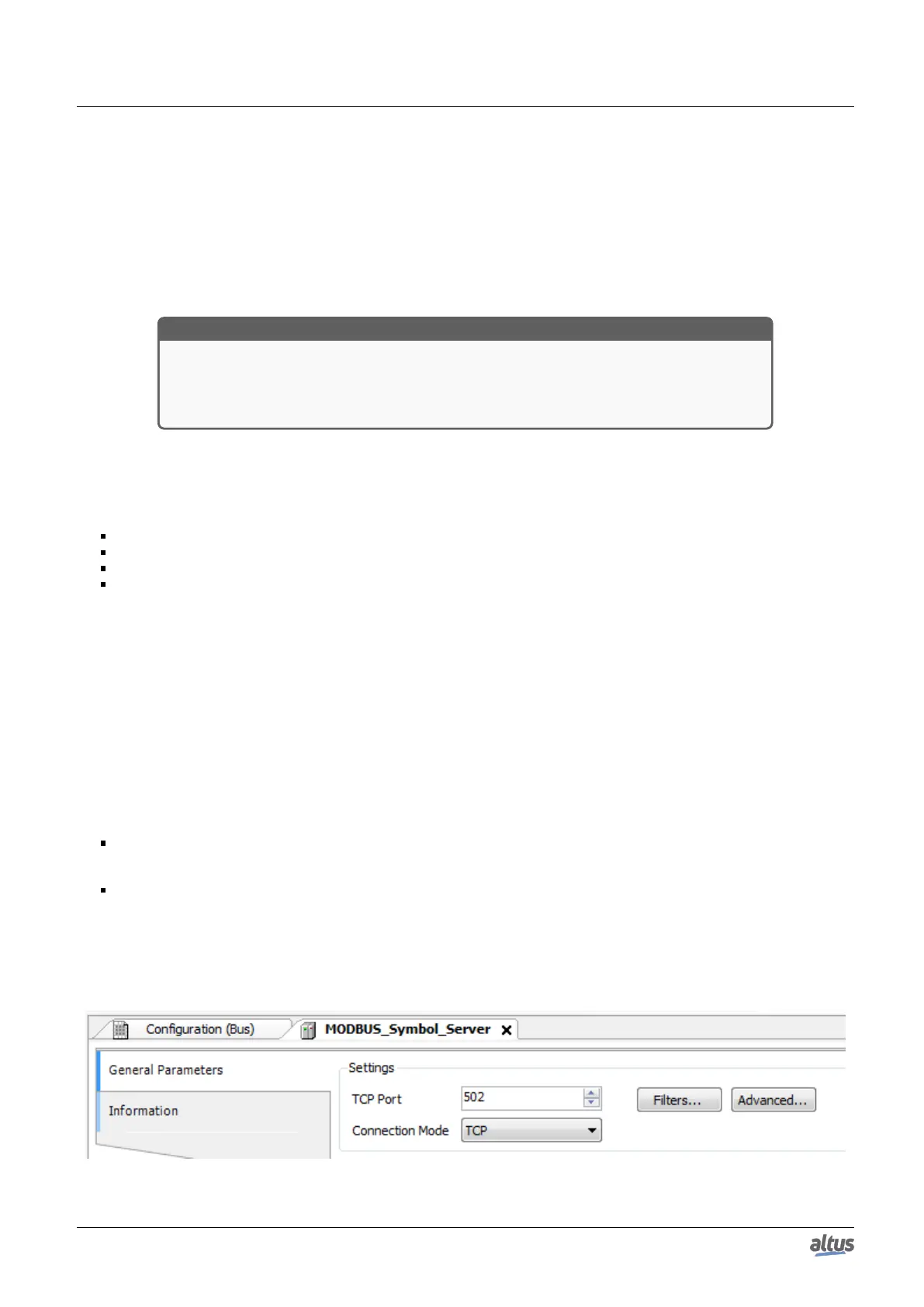
Configure the MODBUS server protocol general parameters, as: TCP port, protocol selection, IP filters for Reading
and Writing (available at the Filters Configuration button) and communication times (available at the Server Advanced
Configurations button).
Add and configure MODBUS mappings, specifying the variable name, data type, data initial address and data size.
The description of each configuration is related ahead in this section.
5.5.9.1.1. MODBUS Server Protocol General Parameters – Configuration via Symbolic Mapping
The general parameters, found on the MODBUS protocol initial screen (figure below), are defined as.
Figure 79: MODBUS Server General Parameters Configuration Screen
143

 Loading...