3. INSTALLATION
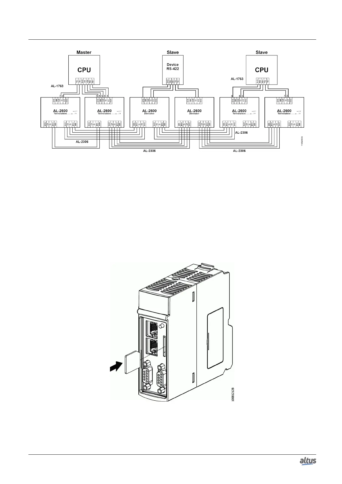
Figure 16: RS-422 Network Example
Diagram Note:
The AL-2600 modules which are in the network endings perform the terminators function. In this case the AL-2600 keys
must be configured in PROFIBUS Termination.
3.6. Memory Card Installation
This section presents how to insert the memory card into the models Nexto Series CPUs. For further information see
Memory Card section.
Initially, care must be taken with the correct position the memory card must be inserted. One corner of it is different from
the other three and this one must be used as reference for the card correct insertion. Therefore, the memory card must be
inserted following the depiction on the CPU frontal part or the way showed on figure below.
Figure 17: Memory Card Insertion in the CPU
When the card is correctly installed, a symbol will appear on the CPU graphic display. For card secure removing the MS
key must be pressed then there is a little delay and the card symbol will disappear from the graphic display. The card is now
30

 Loading...