3. INSTALLATION
3. Installation
This chapter presents the necessary proceedings for the Nexto Series CPUs physical installation, as well as the care that
should be taken with other installation within the panel where the CPU is been installed.
CAUTION
If the equipment is used in a manner not specified by in this manual, the protection provided
by the equipment may be impaired.
3.1. Mechanical Installation
Nexto Series CPUs must be inserted in the backplane rack position 2, just beside the Power Supply Module. All information
regarding mechanical installation and module insertion can be found at MU214600 - Nexto Series User Manual .
3.2. Electrical Installation
DANGER
When executing any installation in an electric panel, certify that the main energy supply is
OFF.
The CPUs energy supply come from the Power Supply Module which supplies the CPUs power through the backplane
rack connection. It does not need any external connection. The module grounding is given through the contact between the
module grounding spring and the backplane rack.
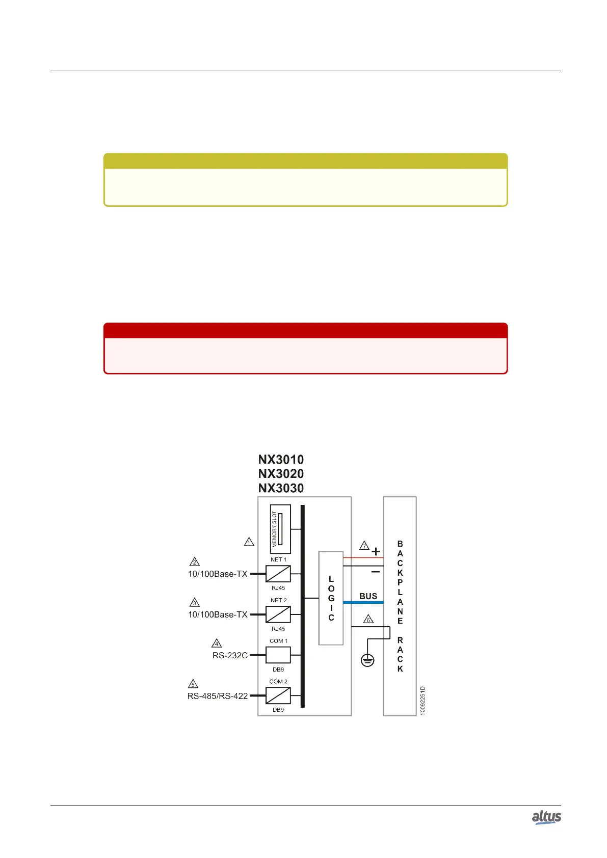
The figure below shows the Nexto Series CPUs electric diagram installed in a Nexto Series backplane rack.
The connectors placement depicted are merely illustrative.
Figure 5: NX3010, NX3020 and NX3030 CPUs Electric Diagram
Diagram Notes:
20

 Loading...