5. CONFIGURATION
5.5.6.1.2. Configuration of the Relations – Symbolic Mapping Setting
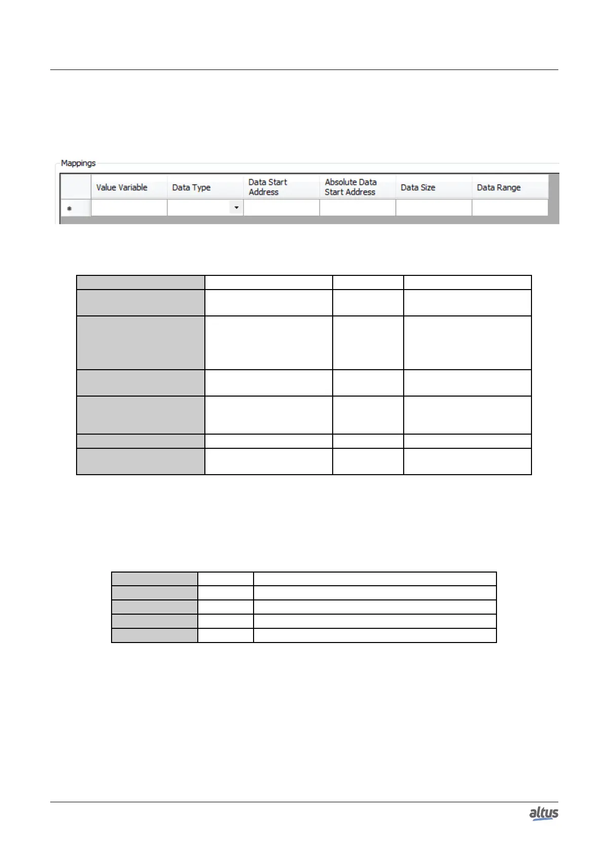
The MODBUS relations configuration, showed on figure below, follows the parameters described on table below:
Figure 66: MODBUS Data Mappings Screen
Configuration Description Default Options
Value Variable Symbolic variable name -
Name of a variable declared
in a program or GVL
Data Type MODBUS data type -
Coil
Input Status
Holding Register
Input Register
Data Start Address
MODBUS data initial ad-
dress
- 1 to 65536
Absolute Data Start Ad-
dress
Absolute initial address of
MODBUS data according to
its type
- -
Data Size MODBUS data size - 1 to 65536
Data Range
Data address range config-
ured
- -
Table 99: MODBUS Mappings Configurations
Notes:
Value Variable: this field is used to specify a symbolic variable in MODBUS relation.
Data Type: this field is used to specify the data type used in the MODBUS relation.
Data Type Size [bits] Description
Coil 1 Digital output that can be read or written.
Input Status 1 Digital input (read only).
Holding Register 16 Analog output that can be read or written.
Input Register 16 Analog input (read only).
Table 100: MODBUS data types supported by Nexto CPUs
Data Start Address: data initial address of the MODBUS relation.
Data Size: the Data Size value sets the maximum amount of data that a MODBUS relation can access from the initial
address. Thus, in order to read a continuous range of addresses, it is necessary that all addresses are declared in a single
relation. This field varies according to the configured type of MODBUS data.
Data Range: this field shows the user the memory address range used by the MODBUS relation.
123

 Loading...