6. REDUNDANCY WITH NX3030 CPU
6.3.16.2. PX2612 LEDs
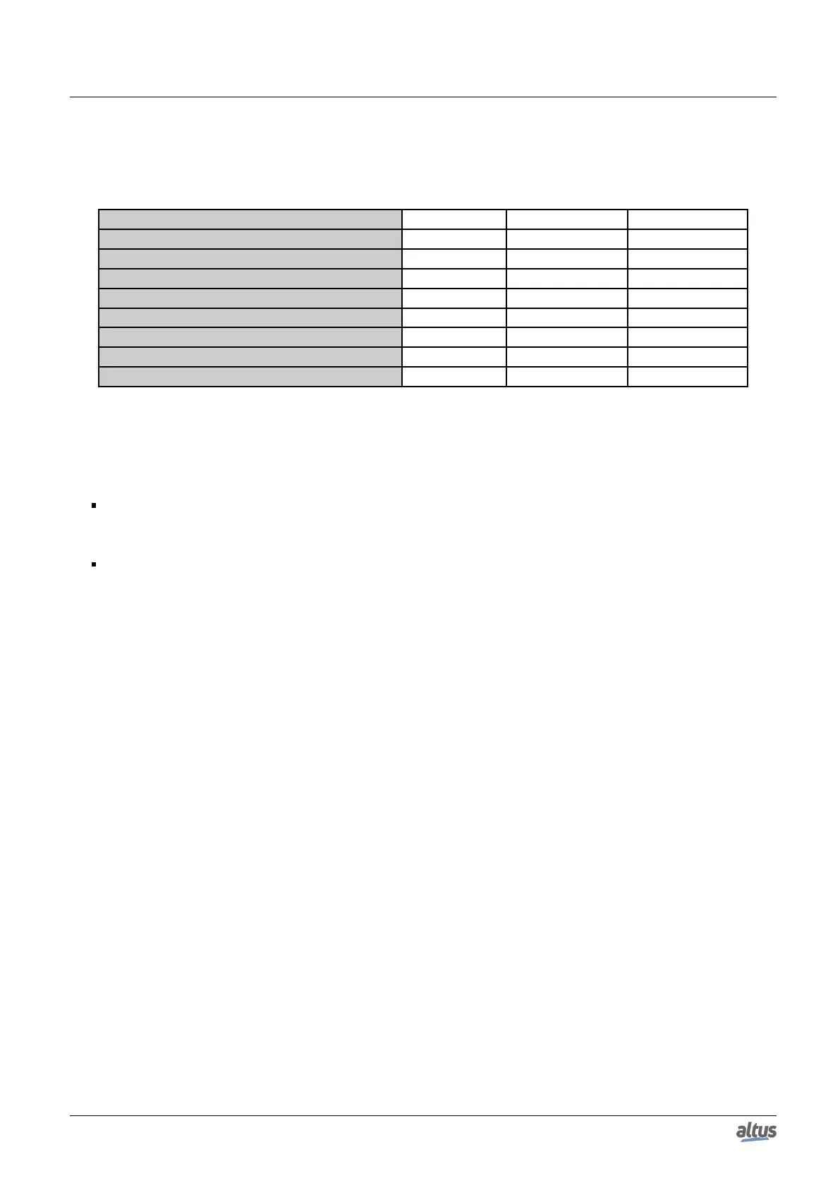
The PX2612 LEDs are used to inform the redundancy state, as shown on the following table below:
Redundancy state LED ACTIVE LED STAND-BY LED INACTIVE
Not-Configured off off off
Starting on on on
Active on off off
Active (recent) blinking off off
Active (switching off the other CPU) on blinking off
Active (recent and switching off the other CPU) blinking blinking off
Stand-by off on off
Inactive off off on
Table 205: PX2612 LEDs
Each LED can be off, on or blinking. In case it’s blinking, it remains on for 0.5 seconds and off for the same time.
Note that there are four different animations for the Active state, due to the following features:
At the first 2 seconds in Active state the ACTIVE LED blinks and remains on afterwards. This animation was created
because in the first instants of the Active state, the CPU won’t accept commands to get out from this state. For further
details regarding this Active CPU behavior, see Transition between Redundancy States and First Instants in Active State
sections
In case this CPU is switching off the other CPU through its PX2612 relay, the LED STAND-BY blinks. It remains off
otherwise
6.3.16.3. PX2612 Relays
The PX2612 has two NO relays. The PLCA can control the RL B, to command the PLCB switching off. The PLCB can
control the RL A, to command the PLCA switching off.
Such switching off situations happen in exceptional situations, described in the Transition between Redundancy States
section.
6.3.17. Transition between Redundancy States
The following figure shows the redundancy state machine, illustrating all the possible transitions between redundancy
states.
296

 Loading...