6. REDUNDANCY WITH NX3030 CPU
6.6.5.4. Buttons Test
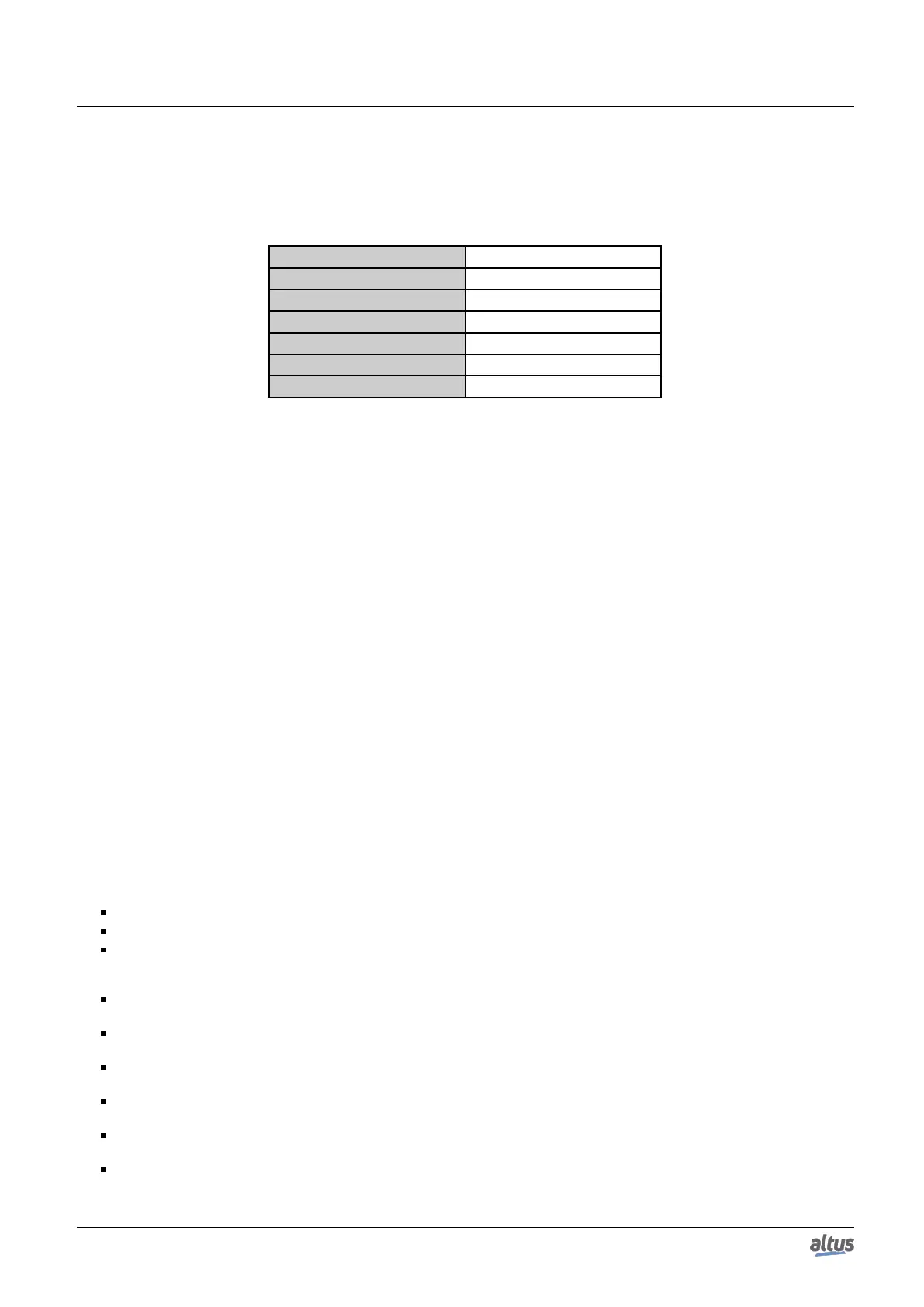
At pressing a button in the test mode, a correspondent LED stops blinking, and remains on. The following table presents
the connection between the pressed button and the LED which remains on.
Tested button Correspondent LED
TURN ON PLC A ACTIVE PLC B
STAND-BY PLC A STAND-BY PLC A
INACTIVE PLC A INACTIVE PLC A
TURN ON PLC B ACTIVE PLC A
STAND-BY PLC B STAND-BY PLC B
INACTIVE PLC B INACTIVE PLC B
Table 216: Connection between buttons and LEDs in the PX2612 button test
It can be observed that normally the LED is on the pressed button side, except for the TURN ON PLCx.
Before the LED remains on, it’s necessary to hold the button for, at least, 1 second. The LED returns to blinking after it’s
released.
During the test mode, the buttons don’t allow the execution of functions which would be executed out of this mode, such
as to cause a redundancy state change.
6.6.5.5. Relay Test
To test the relays, it was created the DG_NX4010.tRedundancy.RedCmdLoc.bTestRelayLocal bit. At turning on this bit,
if the PLC is in test mode and in Active state, it activates the relay, which must cause the other PLC (Non-Active) switching
off. Turning off the DG_NX4010.tRedundancy.RedCmdLoc.bTestRelayLocal, the relay is released, allowing the other PLC
reactivating.
The command has no effect in the Non-Active PLC, to prevent it turns off the Active PLC.
The user must cause a switchover between PLCs (Active x Non-Active) in order to test the relay in both PLCs.
When the PLC which was switched off is reactivated and restarted, it returns with the DG_NX4010.tRedundancy.RedCmdLoc
.bTestModeLocal off, thus the test mode is canceled. The DG_NX4010.tRedundancy.RedCmdLoc.bTestModeLocal bit must
be turned on again in this PLC and set it to Active state before testing its relay.
When the test mode is finished, the DG_NX4010.tRedundancy.RedCmdLoc.bTestRelayLocal command bit is automati-
cally turned off, in case the user has forgotten it on.
6.6.5.6. Suggested Sequence for PX2612 Test Executing
The following sequence is suggested in order to execute the PX2612 tests:
Turn on the DG_NX4010.tRedundancy.RedCmdLoc.bTestModeLocal command bit in both PLCs (PLCA and PLCB).
It must be observed if the 6 LEDs are blinking.
Press, one at a time, the 6 buttons and verify if the correspondent LED stops blinking and remain on while the button is
pressed. It must be remembered the button must remain pressed for, at least, one second before the LED stops blinking
and remains on, and that the LED returns to blinking after the button is released.
Turn on the DG_NX4010.tRedundancy.RedCmdLoc.bTestRelayLocal command bit in the Active PLC. It must be ob-
served the Non-Active PLC switching off.
Turn off the DG_NX4010.tRedundancy.RedCmdLoc.bTestRelayLocal command bit in the Active PLC. It must be ob-
served the Non-Active PLC switching on.
Wait until the Non-Active PLC is restarted and assumes the Stand-by state. The test mode is active as the DG_NX4010
.tRedundancy.RedCmdLoc.bTestModeLocal bit is turned off at the restarting in Stand-by mode PLC.
Cause a switchover between PLCs, pressing the Active PLC STAND-BY button. The normal use of the STAND-BY
button is possible because the test mode isn’t active.
Turn on the DG_NX4010.tRedundancy.RedCmdLoc.bTestModeLocal command bit in the new Active PLC, which has
just gotten out the Stand-by state. This way, the test mode is reactivated.
Turn on the DG_NX4010.tRedundancy.RedCmdLoc.bTestRelayLocal command bit in the Active PLC. It must be ob-
served the Non-Active PLC switching off.
349

 Loading...