5. CONFIGURATION
Direct representation variables (%Q) for the protocol diagnostic:
Configuration Description
Default
Value
Options
%Q Start Address of Diag-
nostics Area
Initial address of the diag-
nostic variables
- 0 to 2147483628
Size Size of diagnostics area 20 Disabled for editing
Table 93: MODBUS RTU Master Configuration
Notes:
Initial Address of Diagnostics in %Q: this field is limited by the size of outputs variables (%Q) addressable memory of
each CPU, which can be found in section Memory.
Default Value: the factory default value cannot be set to the %Q Start Address of Diagnostics Area field, because the
creation of a Protocol instance may be held at any time on application development. The MasterTool IEC XE software itself
allocate a value, from the range of output variables of direct representation (%Q), not used yet.
The diagnostics and MODBUS protocol commands are described in Table 85.
The communication times of the MODBUS Master protocol, found on the button Advanced... in the configuration screen
are divided into Send Delay and Minimum Interframe, further details are described in section MODBUS Master Protocol
General Parameters – Symbolic Mapping Configuration.
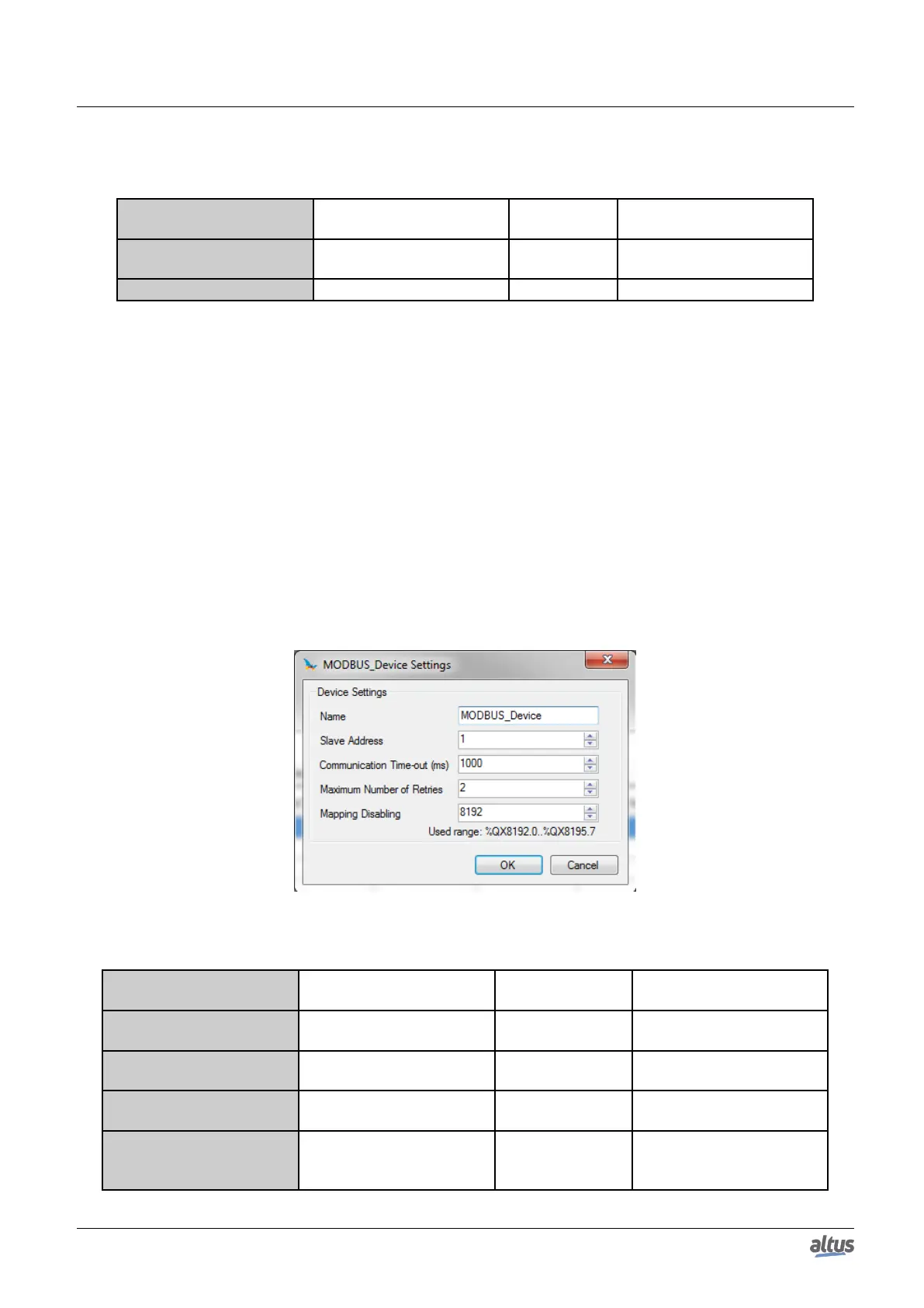
5.5.5.2.2. Devices Configuration – Configuration for Direct Representation (%Q)
The configuration of the devices, viewed in figure below, comprises the following parameters:
Figure 61: Device Configuration
Configuration Description
Default
Value
Options
Name Name of the instance MODBUS_Device
Identifier, according to IEC
61131-3
Slave Address
The MODBUS slave ad-
dress
1 0 to 255
Communication Time-out
(ms)
Sets the time-out of the ap-
plication level
1000 10 to 65535
Maximum Number of Re-
tries
Sets the number of retries
before reporting a communi-
cation error
2 0 to 9
115

 Loading...