6. REDUNDANCY WITH NX3030 CPU
PROFIBUS 1 network:
• %IB0 ... %IB499 (addresses allocated to already installed remotes)
• %IB500 ... %IB999 (addresses allocated to future remotes)
PROFIBUS 2 network:
• %IB1000 ... %IB1499 (addresses allocated to already installed remotes)
• %IB1500 ... %IB1999 (addresses allocated to future remotes)
Modbus TCP server:
• %IB2000 ... %IB2999 (addresses allocated to current mapping)
• %IB3000 ... %IB3999 (addresses allocated to future mapping)
For the two other areas (output %Q and diagnostic %Q) similar examples could be executed.
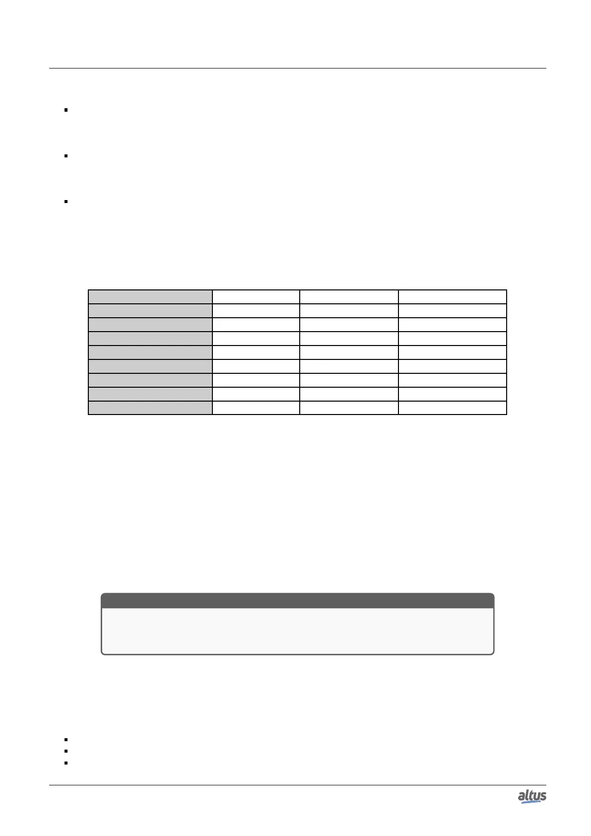
It’s possible to predict the initially allocated and future expansion areas size using the following table which indicates the
byte quantity allocated for the 3 areas for each module:
Module Inputs %I (bytes) Outputs %Q (bytes) Diagnostic %Q (bytes)
NX5001 4 2 86
PO5063V5 0 0 25
PO5065 0 0 25
PO9100 (one each remote) 2 2 10
PO1000 2 0 10
PO2020 0 2 10
PO9999 – 2 bytes Output 0 2 10
PO9999 – 2 bytes Input 2 0 10
Table 208: %I and %Q variables allocation for PROFIBUS network modules
Note:
Variable Allocation: Further information regarding the size and type of memory allocated for each module can be found
in the PROFIBUS-DP NX5001 Master Utilization Manual.
After executing the planning for the 3 areas (initial and final address of each area), the initial addresses must be inserted in
the projected started in step 2.
At first, the parameter “%Q Start Address of Module Diagnostics Area” must be modified in the first NX5001 module, as
shown on the table on the next figure. The planned initial address must be used for the diagnostic %Q variables.
Second, the first network I/O module must be found, starting with the NX5001, which allocate %I variables for inputs. At
finding it, the correspondent “Address” parameter must be altered.
Third, the first network I/O module must be found, starting with the NX5001, which allocate %Q variables for outputs. At
finding it, the correspondent “Address” parameter must be altered.
ATTENTION
At this moment it’s recommended to verify the allocated address range for the 3 variable
areas, verifying if the final addresses of each area are within the planned range, and if there’s
a good free area for expansion for new future remotes insertion.
6.5.7.2. Previous Planning for Other Hot Modifications
There are other hot modifications which, though they don’t affect the PROFIBUS network, also demand offline down-
loading. Next, it’s presented some examples of this type of modifications supported by the procedure which allow executing
modifications offline download without interrupting the process control:
NX5000 modules insertion (Ethernet)
Ethernet or Serial communication I/O driver insertion
Ethernet or Serial communication I/O driver new mapping insertion
326

 Loading...