5. CONFIGURATION
5.1.5. Internal Points
A communication point is storage on the CPU memory under form of two distinct variables. One represents the point’s
value (type BOOL, BYTE, WORD, etc. . . ), while another, represents its quality (type QUALITY). Internal Points are those
which the value and the quality are calculated internally by the user application, that is, they don’t have an external origin like
occur with points linked to IEDs (Communication drivers of type Master/Client) or to local I/O modules.
ATTENTION
Different from what happen with I/O modules declared on local bus, which have its own
quality variables created by MasterTool (IOQualities GVL) and auto updated by the CPU,
I/O modules declared on PROFIBUS remotes don’t have.
It is user responsibility to declare PROFIBUS point’s quality variables, the association of
these quality variables with the value variables at Internal Points tab, as well as genera-
tion and update of the quality variables value, from the existents PROFIBUS diagnostics:
PROFIBUS I/O modules, PROFIBUS head and PROFIBUS Master.
This Internal Points configuration tab’s function is to relate the variable which represents a point’s value with the one
which represents its quality. It must be used to relate value and quality variables internally created on the PLC program (as in
a GVL), which ones typically will be posteriorly mapped to a communication driver, of type Server, for communication with
the control center.
ATTENTION
If a value variable doesn’t own a related quality variable, it will be reported as default a
constant good quality (no significant indication) when the value variable is reported to a
client or control center.
In this way, this tab purpose isn’t to create or declare internal points. To do that, just declare value and/or quality variables
in a GVL and map it on the communication driver.
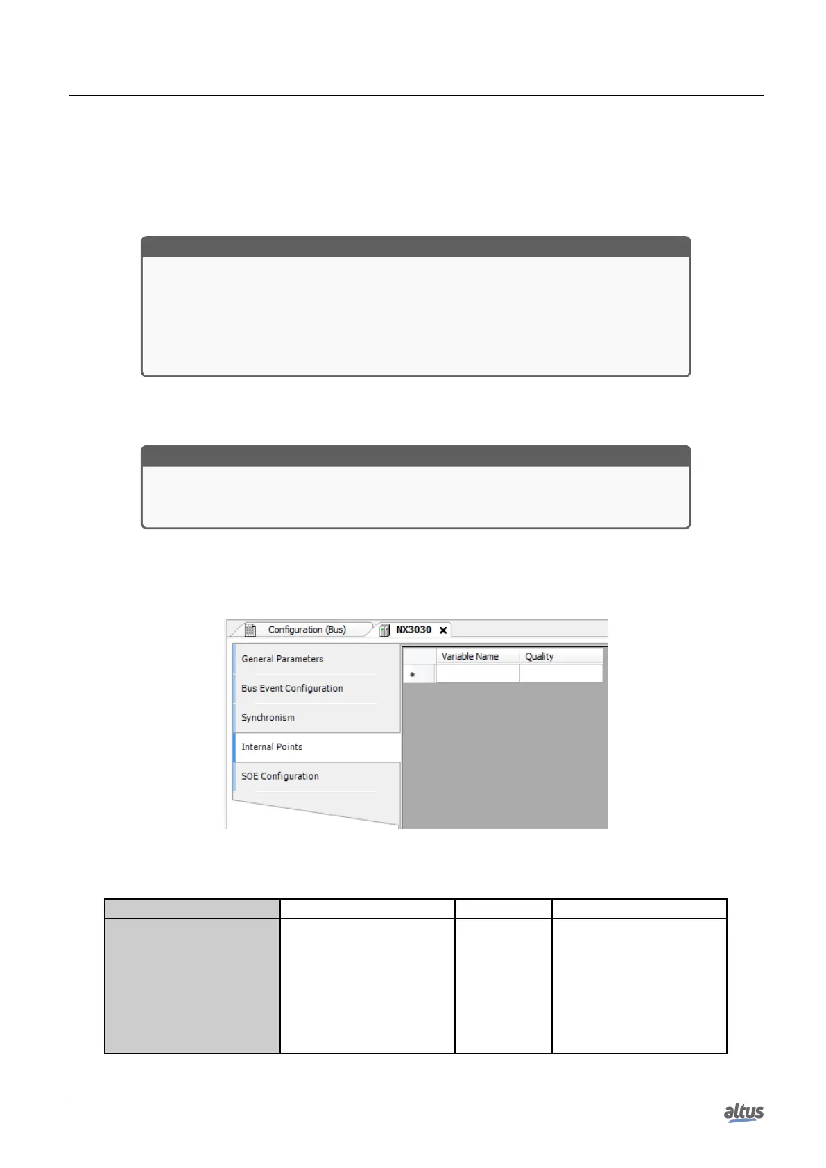
The internal points configuration, viewed on the figure below, follow the parameters described on table below. It’s possible
to configure up to 5120 entries on Internal Points table.
Figure 51: Internal Points Configuration Screen
Configuration Description Default Options
Variable Name
Symbol variable which stor-
age the internal point value
-
Accept variables of type
BOOL, WORD, DWORD,
LWORD, INT, DINT, LINT,
UINT, UDINT, ULINT,
REAL, LREAL or DBP.
The variable can be simple,
array or array’s element and
can be part of a struct.
75

 Loading...