6. REDUNDANCY WITH NX3030 CPU
ATTENTION
The original I/O module bases must be inserted in the first remote rack positions and the
future I/O modules, in the last remote rack positions.
ATTENTION
It must be considered the limitations of the Ponto Series redundant remotes at construct-
ing this list, as the PO5063V1 PROFIBUS Head and PO5063V5 PROFIBUS Redundant
Head Utilization Manual, and PO5064 PROFIBUS Head and PO5065 PROFIBUS Redun-
dant Head Utilization Manual. There are limits regarding the number of modules per remote,
number of bytes per remote, current consuming per power supply, etc. These limits are ver-
ified automatically by the ProPonto. For further information, see the MT6000 MasterTool
ProPonto Utilization Manual - MU299040.
6.5.7.1.2. Step 2 – Insert the Redundant PROFIBUS Network Initial Version in the Project
To insert the redundant PROFIBUS network initial version in the project, initially the two redundant NX5001 modules
must be inserted in the rack, or use those already inserted by the redundancy wizard.
Next, each remote must be inserted in the device tree below these two NX5001, as well as the I/O modules under each
remote.
Regarding the inserted I/O modules, there are two categories that must be treated differently:
Those that are part of the PROFIBUS network initial version and will be installed immediately
Those that will be used for future expansion
In the case of those that are part of the PROFIBUS network initial version, the module itself must be inserted in the device
tree, in the planned remote correspondent position.
In the case of those that will be used for future expansion, a virtual module must be inserted in the planned correspondent
position. A virtual module correspondent to a real module needs to allocate the same amount of I/O bytes than this real module.
The virtual module insertion in the place of a real module avoids the real module absence diagnostics to be produced.
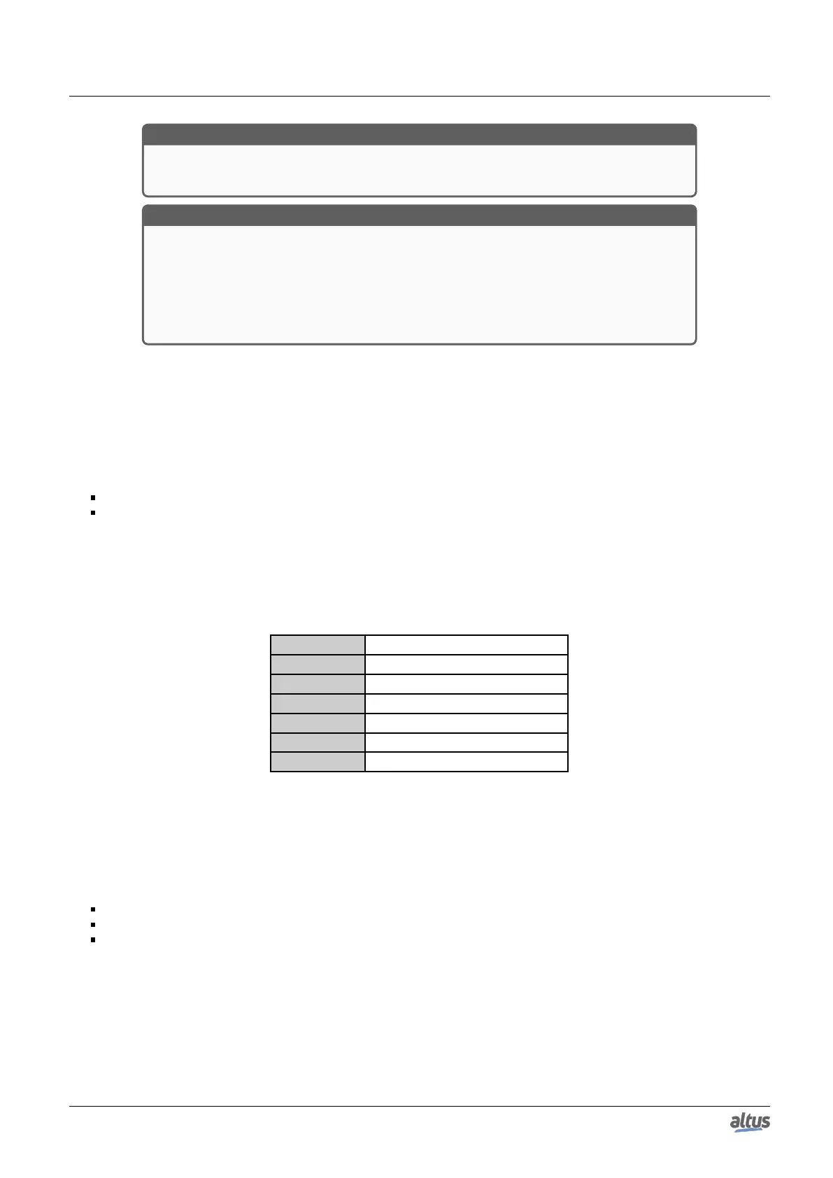
The following table shows real modules and its correspondent virtual modules:
Real Module Correspondent Virtual Module
PO1000 PO9999 – 2 bytes Input
PO1001 PO9999 – 2 bytes Input
PO1002 PO9999 – 2 bytes Input
PO1003 PO9999 – 2 bytes Input
PO2020 PO9999 – 2 bytes Output
PO2022 PO9999 – 2 bytes Output
Table 207: Virtual Modules correspondent to the real modules
6.5.7.1.3. Step 3 – Allocate %I and %Q Variables Areas for the PROFIBUS Network considering Future Remote Expansion
As the NX5001, remotes and I/O modules were being inserted in the device tree in the previous step, %I and %Q variables
were being allocated in three different areas:
%I variables area for inputs
%Q variables area for outputs
%Q variables area for diagnostics
MasterTool executes the allocation of each one of these three variable areas in a continuous way, with no holes between
them.
The initial and final address of each one of these three areas must be planned, considering the initially installed remotes in
the network (see steps 1 and 2), but also remotes which might be inserted in the future in this same PROFIBUS network.
At defining the initial address of each area, it’s important to reserve expansion for the device which allocates addresses
immediately before the beginning of this area. On the other hand, at defining the final address of each area, it’s important to
reserve expansion for this PROFIBUS network.
Next, an example of such planning is shown, for %I variables area for inputs:
325

 Loading...