6. REDUNDANCY WITH NX3030 CPU
6.2.4.1. PX2612 Features
The redundancy control panel PX2612 has the following features:
CONTROL PLC A: connection to the module NX4010 from PLCA
CONTROL PLC B: connection to the module NX4010 from PLCB
RL A: relay NO terminals used to switch off PLCA
RL B: relay NO terminals used to switch off PLCB
GND: grounding
Other features (generals, electrical, mechanic and environment) are presented in the Redundancy Control Panel PX2612
Technical Characteristics - CT112500.
6.2.5. Interconnections between Half-Clusters and the Redundancy Control Panel PX2612
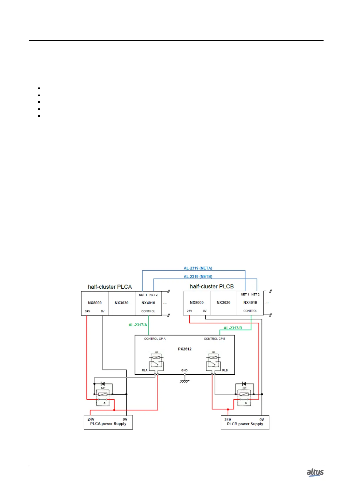
The figure below shows how the connections between PLCA, PLCB and PX2612 have to be made, including the possibility
to allow a CPU to switch off the other, which is necessary in exceptional situations.
Two AL-2319 cables must be used for the synchronism and redundancy channels NETA and NETB. One of these two cables
interconnects the NX4010 NET 1 connector from each CPU (NETA channel). The other cable interconnects the NX4010 NET
2 connector from each CPU (NETB channel).
An AL-2317/A cable interconnects the NX4010 CONTROL connector from the PLCA to the PX2612 CONTROL PLC A.
An AL-2317/B cable interconnects the NX4010 CONTROL connector from the PLCB to the PX2612 CONTROL PLC B.
Besides this, it’s necessary to build a special power supply circuit in order to allow a CPU to switch off the other in extreme
cases.
For higher reliability, two separate 24 V power supplies must be used, one for PLCA supply and other for PLCB supply.
It can be observed that is necessary to use two external relays from the normally closed type (NC), with current capacity
to feed the NX8000. These relays must be dimensioned for a nominal current around 2 A, however, a current inrush of around
10 A must be taken into account. Shunt diodes connected to the NC relays solenoids must be used to protect the PX2612 NO
relay contacts.
Figure 169: Interconnections between PLCA, PLCB and PX2612
274

 Loading...