3. INSTALLATION
1. The not connected terminals must be insulated so they do not make contact with each other.
3.5.3. RS-485 Communication with External Termination
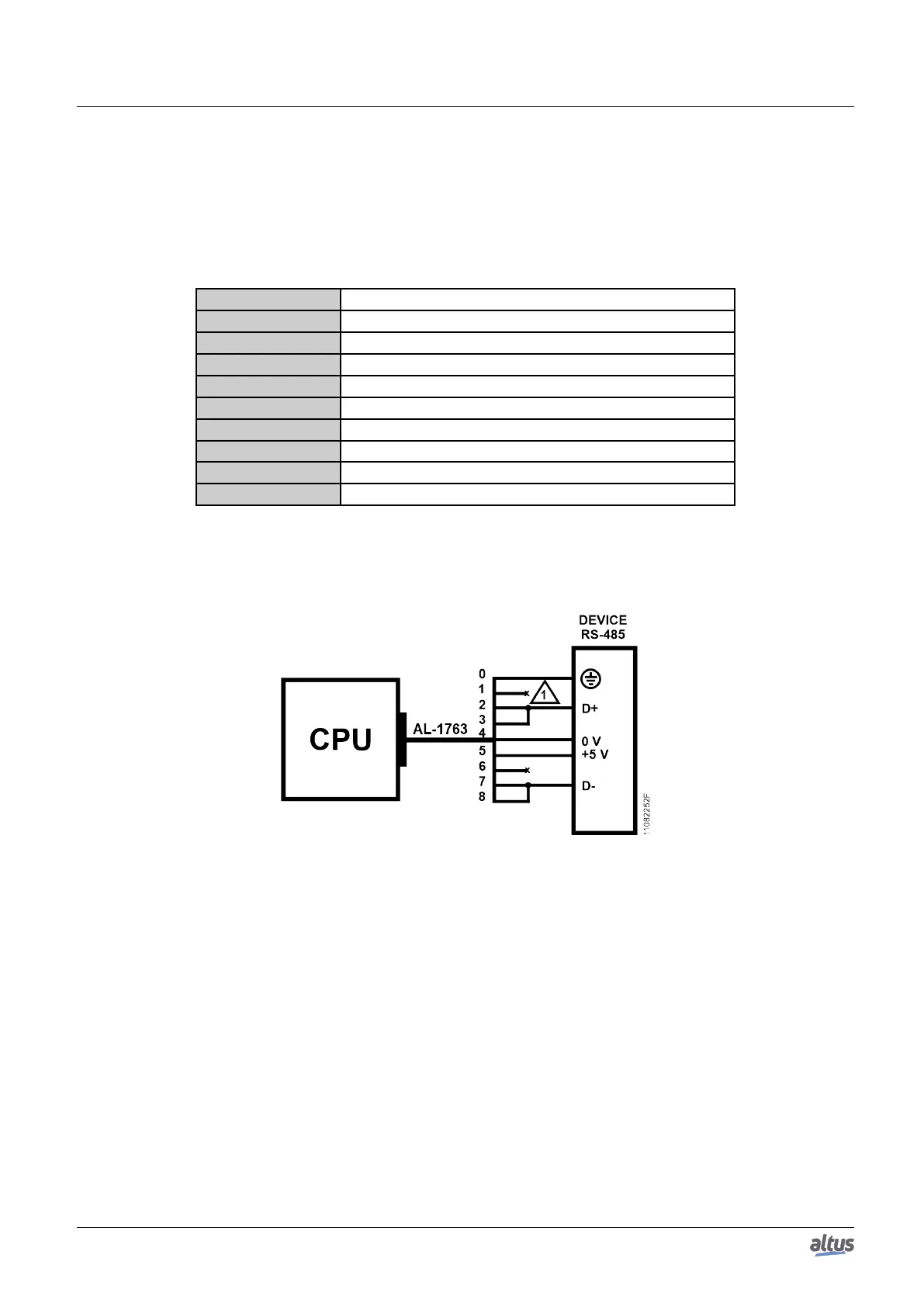
In order to connect to a RS-485 network wih external termination, the AL-1763 cable identified terminals must be con-
nected in the respective device terminals according to the table below.
AL-1763 terminals CPU terminal signals
0 Shield
1 Not connected
2 D+
3 D+
4 0 V
5 +5 V
6 Not connected
7 D-
8 D-
Table 27: RS-485 Connections with External Termination
The figure diagram below indicates how the AL-1763 connection terminals should be connected in the device terminals.
Figure 11: RS-485 Connections with External Termination Diagram
Diagram Note:
1. The not connected terminals must be insulated so they do not make contact with each other.
3.5.4. Example of Connection of a RS-485 Network with External Termination and Master Redundancy
The figure below shows an example of RS-485 network connection with external termination, using two Nexto NX3030
CPUs with half-cluster redundancy as master.
26

 Loading...