7. MAINTENANCE
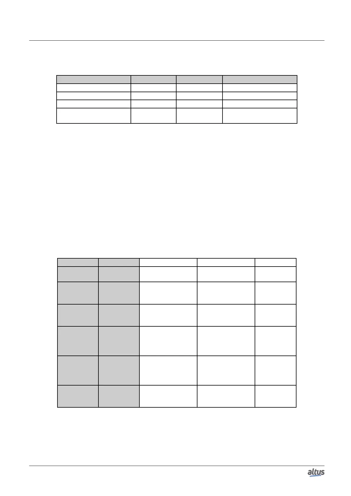
The table below shows the difference between the short touch time, the long touch time and stuck button.
Touch type Minimum time Maximum time Indication condition
No touch - 59.99 ms -
Short touch 60 ms 0.99 s Release
Long touch 1 s 20 s More than 1 s till 20 s
Locked Switch 20.01 s (∞)
Diagnostics indication, see
on Table 222
Table 217: One Touch Time
The messages presented on the Nexto CPU graphic display, correspondent to the diagnostics, are described in the Diag-
nostics via Variables section, on Table 222.
If any situation of stuck button occur in one of the I/O modules, the diagnostic button of this module will stop of indicate
the diagnostics on CPU graphic display when is pressed. In this case, the CPU will indicate that there is a module with active
diagnostics. To remove this diagnostic from the CPU, a hot swap must be done in the module where the diagnostic is active.
For further details on the procedure for viewing the diagnostics of the CPU or other bus modules, see description in the
User Manual Nexto Series – MU214600.
7.1.2. Diagnostics via LED
This product have a LED for diagnostic indication (LED DG) and a LED for watchdog event indication (LED WD). The
Tables 218 and 219 show the meaning of each state and its respective descriptions.
7.1.2.1. DG (Diagnostic)
Green Red Description Causes Priority
Off Off Not used
No power supply.
Hardware problem
-
On Off
All applications
in execution mode
(Run)
- 3 (Low)
Off On
All applications
in stopping mode
(Stop)
- 3 (Low)
Blinking 2x Off
Bus modules with di-
agnostic
At least, a bus mod-
ule, including the
CPU, is with an
active diagnostic
1
Blinking 3x Off Data forcing
Some memory area is
being forced by the
user through Master-
Tool IEC XE
2
Off Blinking 4x
Configuration or
hardware error in the
bus
The bus is damaged
or is not properly
configured
0 (High)
Table 218: Description of the Diagnostic LEDs States
7.1.2.2. WD (Watchdog)
353

 Loading...