7. MAINTENANCE
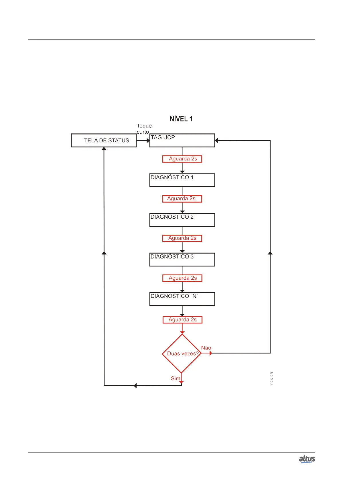
the IEC 61131-3 standard), in other words, the name attributed to the CPU, and after that all diagnostics are shown, through
CPU display messages. This process is executed twice on the display. Everything occurs automatically as the user only has to
execute the first short touch and the CPU is responsible to show the diagnostics. The diagnostics of other modules present on
the bus are also shown on the CPU graphic display by a short press in the diagnostic module button, in the same presentation
model of diagnostics.
The figure below shows the process starting with the short touch, with the conditions and the CPU times presented in
smaller rectangles. It is important to stress the diagnostics may have more than one screen, in other words, the specified time
in the block diagram below is valid for one of them.
Figure 190: CPU Diagnostics Visualization
Before all visualization process be concluded, it is just to give a short touch on the diagnostic switch, at any moment, or
press the diagnostic switch from any I/O module connected to the bus. Also, it is important to observe that the One Touch Diag
could be available when the module could be in Operational Mode.
In case a long touch is executed, the CPU goes to navigation menu, which is described in the Configuration – CPU’s
Informative and Configuration Menu section.
352

 Loading...