7. MAINTENANCE
7.2. Graphic Display
The graphic display available in this product has an important tool for the process control, as through it is possible to
recognize possible error conditions, active components or diagnostics presence. Besides, all diagnostics including the I/O
modules are presented to the user through the graphic display. For further information regarding the diagnostic key utilization
and its visualization see One Touch Diag section.
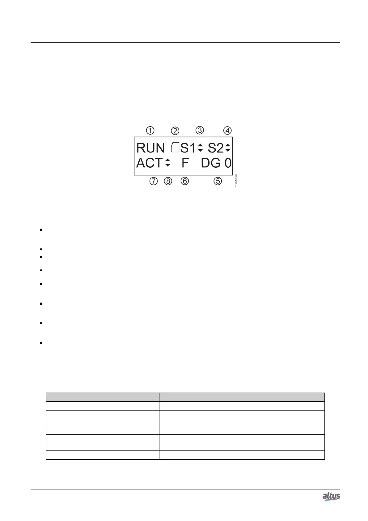
On figure below, it is possible to observe the available characters in this product graphic display and, next, its respective
meanings.
Figure 197: CPU Status Screen
Legend:
1. Indication of the CPU status operation. In case the CPU application is running, the state is RUN. In case the CPU
application is stopped, the state is STOP and, when is stopped in an application depuration mark, the state is BRKP. For
further details, see CPU Operating States section.
2. Memory Card presence indication. Further details regarding its installation see Memory Card Installation section.
3. COM 1 traffic indication. The up arrow (▲) indicates data transmission and the down arrow (▼) indicates data
reception. For further information regarding the COM 1 interface see Serial Interfaces section.
4. COM 2 traffic indication. The up arrow (▲) indicates data transmission and the down arrow (▼) indicates data
reception. For further information regarding the COM 2 interface see Serial Interfaces section.
5. Indication of the CPU active diagnostics quantity. In case the number shown is different than 0 (zero), there are active
diagnostics in the CPU. For further details regarding their visualization on the CPU graphic display, through diagnostic
key, see One Touch Diag section.
6. Forced variables in the CPU indication. In case the “F” character is shown in the graphic display, a variable is being
forced by the user, whether symbolic, direct representation or AT. For further information regarding variable forcing see
Writing and Forcing Variables section.
7. Identification of the CPU redundancy state (message only valid in NX3030 in redundant mode). If the CPU is the
active PLC, the ACT information will be presented. The other possible states are NCF (Not-configured), STR (Starting),
INA (Inactive) and SBY (Stand-by).
8. Indication that the project synchronization is being executed. The up arrow (▲) indicates project data transmission
and the down arrow (▼) indicates project data reception. For further information about the project synchronization see
Project Synchronization section.
Besides the characters described above, Nexto CPUs can present some messages on the graphic display, correspondent to
a process which is being executed at the moment.
The table below present the messages and their respective descriptions:
Message Description
FORMATTING... Indicates the CPU is formatting the memory card.
FORMATTING ERROR
Indicates that an error occurred while formatting the memory
card by the CPU.
WRONG FORMAT Indicates that the memory card format is incorrect.
INCORRECT PASSWORD
Indicates the typed password is different from the configured
password.
TRANSFERRING... Indicates the project is being transferred.
372

 Loading...