5. CONFIGURATION
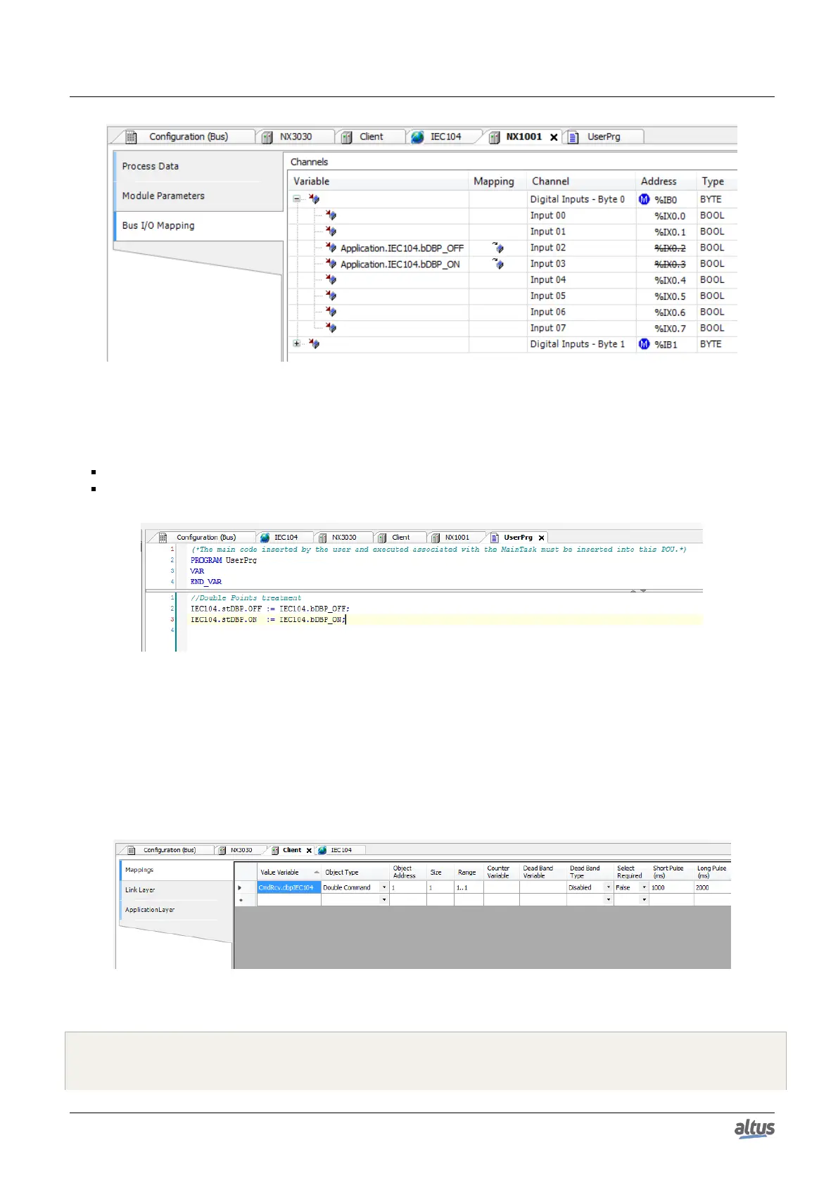
Figure 120: Variables Mapping at the Module Inputs
At last, the user must insert two code lines in its application, to be cyclically executed, to simple variables value attribution
to double point:
DBP value variable, index ON, receive simple point ON value
DBP value variable, index OFF, receive simple point OFF value
Figure 121: Variables’ Values Attribution to the Double Point
5.5.14.2.2. Digital Output Double Points
For the digital output modules it must be used the CommandReceiver function block to intercept double points actuation
commands originated from the clients IEC 60870-5-104. Consult the section Interception of Commands Coming from the
Control Center for further information.
The example code below, POU CmdRcv, treats pulsed commands received from clients for a digital double point, mapped
in a NX2020 module. Besides the following ST code it is need to map a DBP point in Nexto’s IEC 60870-5-104 server.
Figure 122: Mapping of Digital Output Double Point variables on IEC 60870-5-104 Client
PROGRAM CmdRcv
VAR
CmdReceive: CommandReceiver; // Interceptor Instance
200

 Loading...