5. CONFIGURATION
Configuration Description Default Value Options
%Q Start Address of Diag-
nostics Area
Initial address of the diag-
nostic variables
- 0 to 2147483628
Size Size of diagnostics area - Disabled for editing
Slave Address MODBUS slave address 1 1 to 255
Mapping Disabling
Initial address used to dis-
able MODBUS relations
- 0 to 2147483644
Table 101: Address and Direct Representation Variables Settings
Notes:
%Q Start Address of Diagnostics Area: this field is limited by the size of output variables addressable memory (%Q) of
each CPU, which can be found in section Memory.
Slave Address: it is important to note that the Slave accepts requests broadcast, when the master sends a command with
the address set to zero. Moreover, in accordance with standard MODBUS, the valid address range for slaves is 1 to 247. The
addresses 248 to 255 are reserved.
Mapping Disabling: composed of 32 bits, used to disable, individually, the 32 MODBUS relations configured in Slave
Mappings space. The relation is disabled when the corresponding bit is equal to 1, otherwise, the mapping is enabled. This
field is limited by the size of output variables addressable memory (%Q) of each CPU, which can be found on Memory section.
Default Value: the factory default value cannot be set for the %Q Start Address of Diagnostics Area and Mapping Dis-
abling fields, since the creation of a relation can be performed at any time on application development. The MasterTool IEC
XE software itself allocate a value from the range of direct representation output variables (%Q), still unused.
The MODBUS protocol diagnostics and commands are described in the Table 98.
The communication times of the MODBUS Slave protocol, found on the button Advanced... of the configuration screen,
are described in Table 97.
5.5.6.2.2. Mappings Configuration – Configuration via Direct Representation (%Q)
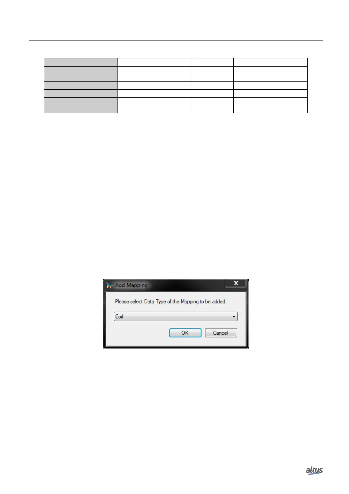
The MODBUS relations settings, viewed in the figures below, follow the parameters described in table below:
Figure 68: Adding MODBUS Relations
125

 Loading...