5. CONFIGURATION
Figure 69: Configuring the MODBUS Relation
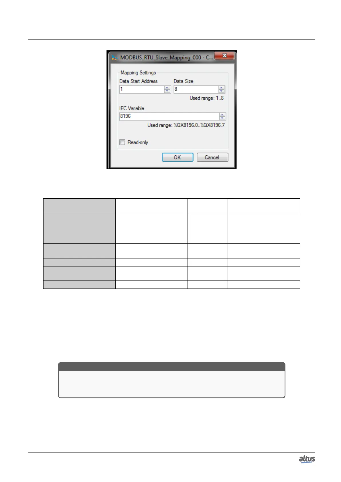
Configuration Description
Default
Value
Options
Data Type MODBUS data type Coil
Coil (1 bit)
Holding Register (16 bits)
Input Register (16 bits)
Input Status (1 bit)
Data Start Address
Initial address of the MOD-
BUS data
1 1 to 65536
Data Size Number of MODBUS data - 1 to 65536
IEC Variable
Initial address of variables
(%Q)
- 0 to 2147483647
Read-only Only allows reading Disabled Enabled or disabled
Table 102: Slave Mappings
Notes:
Options: the values written in the column Options may vary according with the configured MODBUS data.
Data Size: the value of Data Size defines the maximum amount of data that a MODBUS relation can access, from the
initial address. Thus, to read a continuous address range, it is necessary that all addresses are declared in a single interface.
This field varies with the MODBUS data type configured, i.e. when selected Coil or Input Status, the Data Size field must be a
multiple of eight. Also, the maximum amount must not exceed the size of output addressable memory and not assign the same
values used in the application.
ATTENTION
When accessing the communication data memory is between devices with different endian-
ism (Little-Endian and Big-Endian), inversion of the read/write data may occur. In this case,
the user must adjust the data in the application.
IEC Variable: in case the MODBUS data type is Coil or Input Status (bit), the IEC variables initial address will be in the
format %QX10.1. However, if the MODBUS data type is Holding Register or Input Register (16 bits), the IEC variables initial
address will be in the format %QW. This field is limited by the memory size of the addressable output variables (%Q) from
each CPU, which can be seen on Memory section.
Read-only: when enabled, it only allows the communication master to read the variable data. It does not allow the writing.
This option is valid for the writing functions only.
126

 Loading...