5. CONFIGURATION
5.5.8.1.1. MODBUS Client Protocol General Parameters – Configuration via Symbolic Mapping
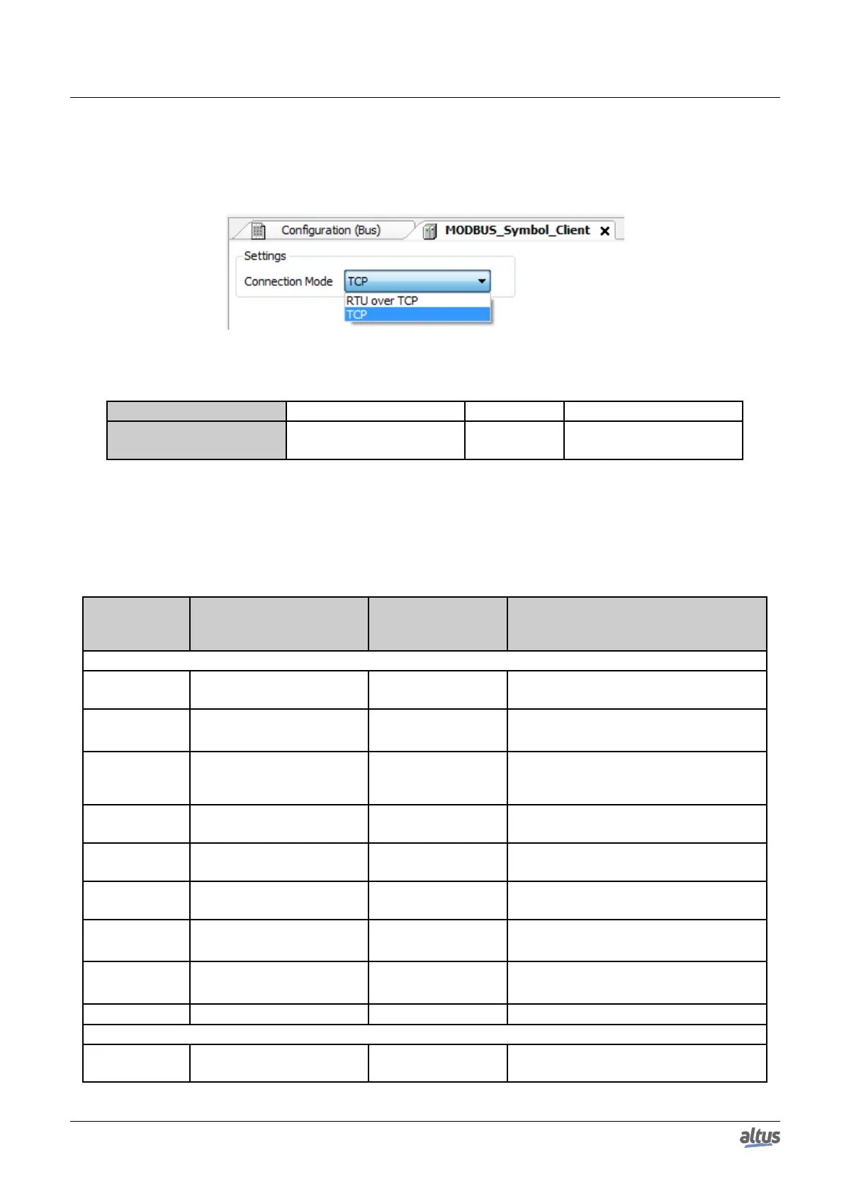
The general parameters, found on the MODBUS protocol configuration initial screen (figure below), are defined as:
Figure 71: MODBUS Client General Parameters Configuration Screen
Configuration Description Default Options
Connection Mode Protocol selection TCP
RTU via TCP
TCP
Table 105: MODBUS Client General Configurations
The MODBUS Client protocol diagnostics and commands configured, either by symbolic mapping or direct representation,
are stored in T_DIAG_MODBUS_ETH_CLIENT_1 variables. For the direct representation mapping, they are also in 4 bytes
and 8 words which are described in table below (where “n” is the configured value in the %Q Start Address of Diagnostics
Area):
Direct Repre-
sentation
Variable
Diagnostic Variable
T_DIAG_MODBUS
_ETH_CLIENT_1.*
Size Description
Diagnostic Bits:
%QX(n).0
tDiag.
bRunning
BIT The client is in execution mode.
%QX(n).1
tDiag.
bNotRunning
BIT
The client is not in execution mode (see bit
bInterruptedByCommand).
%QX(n).2
tDiag.
bInterruptedByCommand
BIT
The bit bNotRunning was enabled, as the
client was interrupted by the user through
command bits.
%QX(n).3
tDiag.
bConfigFailure
BIT Discontinued diagnostics.
%QX(n).4
tDiag.
bRXFailure
BIT Discontinued diagnostics.
%QX(n).5
tDiag.
bTXFailure
BIT Discontinued diagnostics.
%QX(n).6
tDiag.
bModuleFailure
BIT
Indicates if there is failure in the module or
the module is not present.
%QX(n).7
tDiag.
bAllDevicesCommFailure
BIT
Indicates that all devices configured in the
Client are in failure.
%QB(n+1)
byDiag_1_reserved
BYTE Reserved.
Command bits, automatically initialized:
%QX(n+2).0
tCommand.
bStop
BIT Stop client.
130

 Loading...