3. INSTALLATION
It is important to stress that it is understood by network cable a pair of RJ45 male connectors connected by a UTP or ScTP
cable, category 5 whether straight connecting or cross-over. It is used to communicate two devices through the Ethernet port.
These cables normally have a connection lock which guarantees a perfect connection between the interface female con-
nector and the cable male connector. At the installation moment, the male connector must be inserted in the module female
connector until a click is heard, assuring the lock action. To disconnect the cable from the module, the lock lever must be used
to unlock one from the other.
3.4. Serial Network Connection RS-232
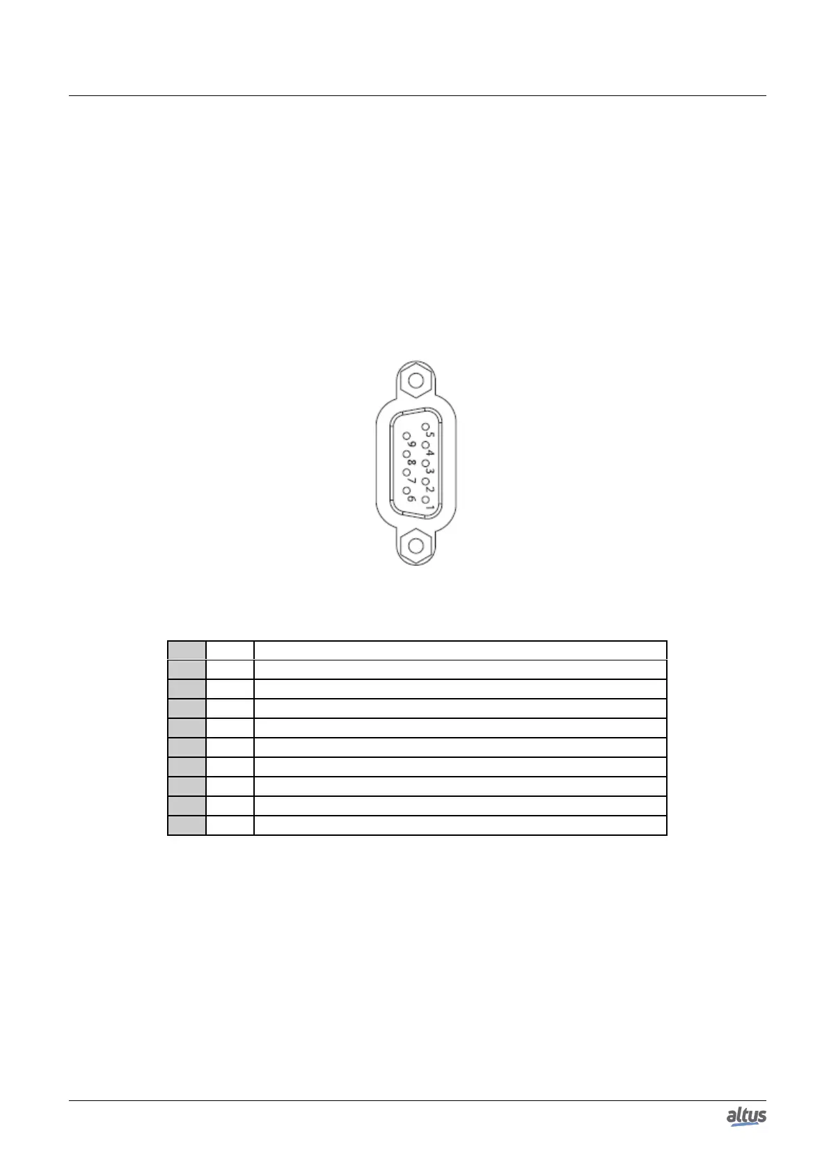
The COM 1 non isolated communication interface allows the connection to a RS-232C network. As follows it’s presented
the DB9 female connector to Nexto CPU, with identification and sign description.
Figure 7: DB9 Female Connector
Pin Sign Description
1 DCD Data Carrier Detect
2 TXD Data Transmission
3 RXD Data Reception
4 - Not used
5 GND Ground
6 - Not used
7 CTS Clear to Send
8 RTS Request to Send
9 - Not used
Table 23: COM 1 DB9 Female Connector Pin Layout
3.4.1. RS-232C Communication
For connection to a RS-232C device, use the appropriate cable as the section Related Products.
3.5. Serial Network Connection RS-485/422
The COM 2 isolated communication interface allow the connection to a RS-485/422 network. As follows it’s presented
the DB9 female connector to Nexto CPU, with identification and sign description.
23

 Loading...