6. REDUNDANCY WITH NX3030 CPU
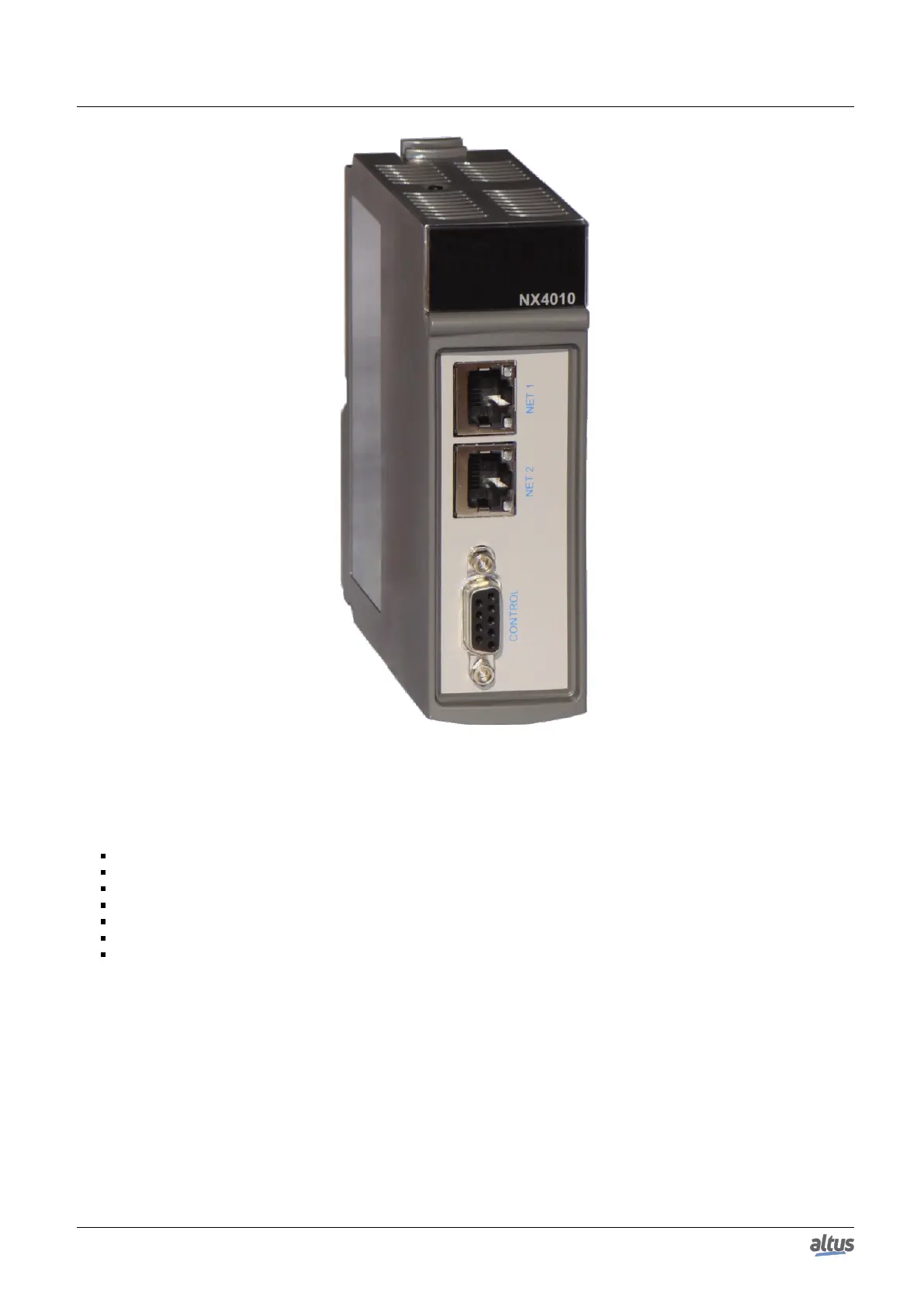
Figure 166: NX4010
6.2.3.1. NX4010 Features
Its main features are:
Data and application synchronization between two half-clusters
Redundant communication interface between two half-clusters
Automatic switchover (active half-cluster change) in case of NX4010 and CPU communication time-out
Possibility to switch off the other half-cluster
One Touch Diag
Electronic Tag on Display
Display and LEDs for diagnostics indication
Other features (generals, electrical, mechanic and environment) are presented in the NX4010 Redundancy Module Techni-
cal Characteristics - CE114900.
6.2.4. Redundancy Control Panel PX2612
The PX2612 control panel is an optional item in a redundant system. It must be used when the ‘redundancy with panel’
option is selected during the project creation using the wizard. Figure 167 shows the redundancy control panel, while Figure
168 shows the frontal panel with details.
Through the DB9 connector called CONTROL PLC A, the connection with the CONTROL connector from PLCA NX4010
is made, using the AL-2317/A cable.
Through the DB9 connector called CONTROL PLC B, the connection with the CONTROL connector from PLCB NX4010
is made, using the AL-2317/B cable.
Furthermore, there’s a connector with 5 male terminals:
272

 Loading...