6. REDUNDANCY WITH NX3030 CPU
GND: terminal for ground connection.
RL A: 2 terminals connected to a relay NO (normally open) contacts, which can be commanded by PLCB to switch off
PLCA. This relay must be closed by PLCB in order to switch off PLCA.
RL B: 2 terminals connected to a relay NO (normally open) contacts, which can be commanded by PLCA to switch off
PLCB. This relay must be closed by PLCA in order to switch off PLCB.
A CPU (PLCA or PLCB) can turn off the other CPU (PLCB or PLCA) in some exceptional situations, using the NO relays
in the RLA and RLB connectors. Such situations are described in the Transition between Redundancy States section.
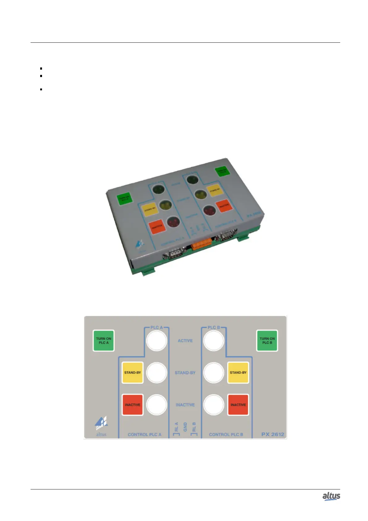
The PX2612 has also 6 buttons for redundancy command and 6 LEDs used for redundancy state indication. Each CPU
reads 3 from these 6 buttons and controls 3 LEDs.
For further information regarding these buttons and LEDs functions, see PX2612 Redundancy Command Panel Functions
section.
Figure 167: Redundancy Control Panel PX2612
Figure 168: Redundancy Control Panel PX2612 Frontal View
273

 Loading...