3. INSTALLATION
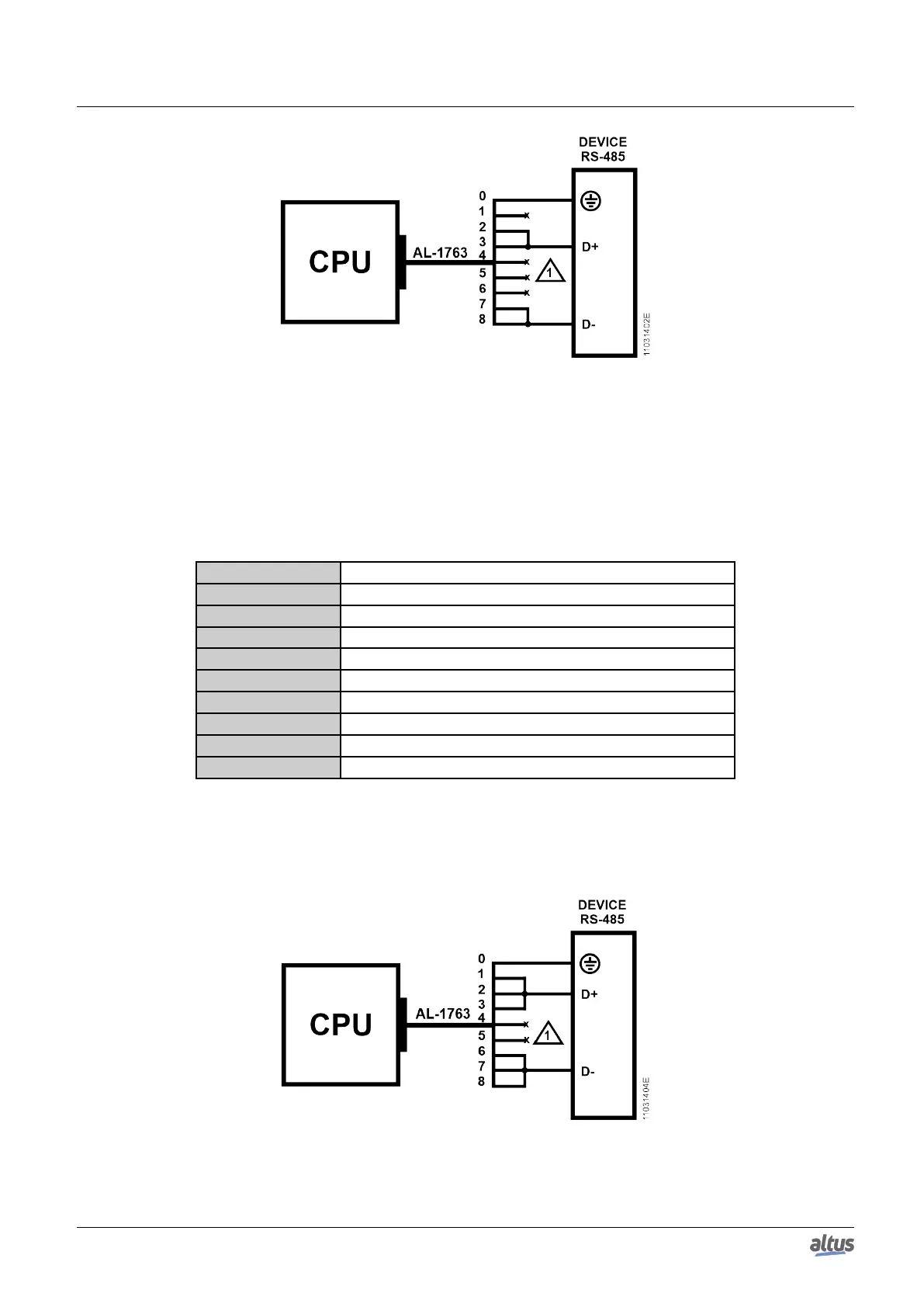
Figure 9: RS-485 Connections without Termination Diagram
Diagram Note:
1. The not connected terminals must be insulated so they do not make contact with each other.
3.5.2. RS-485 Communication with Internal Termination
In order to connect in a RS-485 network using the internal termination, the cable AL-1763 identified terminals must be
connected in the respective device terminals, as shown on table below.
AL-1763 terminals CPU terminal signals
0 Shield
1 D+
2 D+
3 D+
4 Not connected
5 Not connected
6 D-
7 D-
8 D-
Table 26: RS-485 Connections with Internal Termination
PS.: The internal termination available is a safe state type in open mode.
The figure diagram below indicates how the AL-1763 connection terminals should be connected in the device terminals.
Figure 10: RS-485 Connections with Internal Termination Diagram
Diagram Note:
25

 Loading...