5. CONFIGURATION
Parameter Description
Factory De-
fault
Possibilities
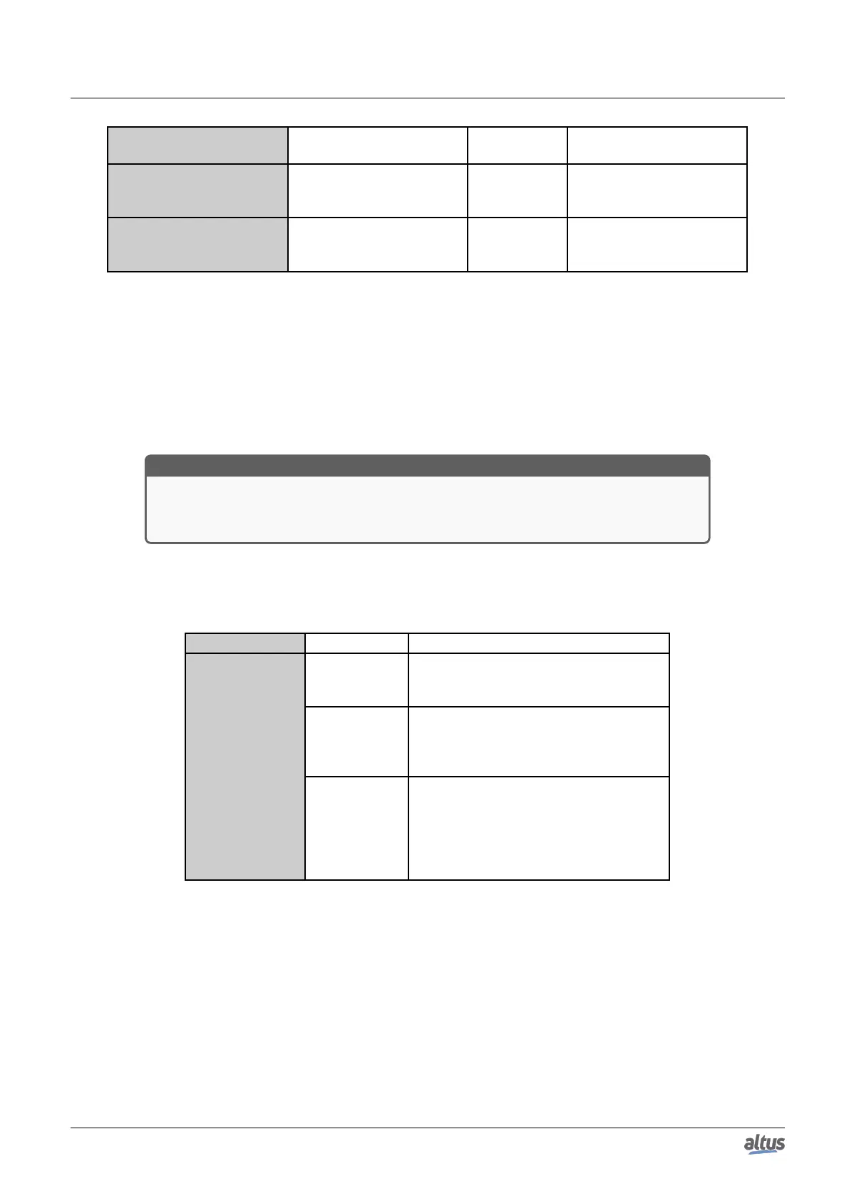
Short Pulse (ms)
Defines the short pulse time
to an IEC 60870-5-104 digi-
tal command
1000 1 to 86400000
Long Pulse (ms)
Defines the long pulse time
to an IEC 60870-5-104 digi-
tal command
2000 1 to 86400000
Table 144: IEC 60870-5-104 Server Mappings Configuration
Notes:
Value Variable: When a read command is sent, the return received in the answer is stored in this variable. When it is a
write command, the written value is going to be stored in that variable. The variable can be simple, array, array element or can
be at structures.
Counter Variable: This field applies only on mapping of Integrated Totals type objects, being this the controller variable
to be managed on process. It must has same type and size of the variable declared on Value Variable column, which value is
going to be read, or reported to, the client in case of events.
ATTENTION
When the Counter Variable has a quality variable associated, to the quality to be transferred
to the frozen variable at freeze command, it must be associated a quality variable to the
frozen one. This procedure must be done through Internal Points tab.
Dead Band Variable: This field applies only to input analog variables (Measured Value type objects) mappings. It must
has same type and size of the variable declared on Value Variable column. New dead band variable values are going to be
considered only when the input analog variable change its value.
Dead Band Type: The configuration types available to dead band are:
Function type Configuration Description
Disabled
In this option, any value change in a
group’s point, as smaller it is, generates an
event to this point.
Dead Band Type Absolute
In this option, if the group’s point value ab-
solute change is bigger than the value in
“Dead Band” field, an event is going to be
generated to this point.
Integrated
In this option, if the absolute of the inte-
gration of the group’s point value change
is bigger than the value in “Dead Band”
field, an event is going to be generated to
this point. The integration interval is one
second.
Table 145: IEC 60870-5-104 Server Mappings Dead Band Types
Short Pulse and Long Pulse: At the define of short and long pulses duration time it must be considered the limits
supported by the device which will treat the command. For example, case the destiny is an output card, which is not supported
in native by Nexto Series. It must be checked at the module’s Datasheet what the minimum and maximum times, as well as
the resolution, to running the pulsed commands.
5.5.14.5. Link Layer
To the IEC 60870-5-104 Server link layer parameters configuration, shown on figure below, follow the described parameters
on table below:
207

 Loading...