2. TECHNICAL DESCRIPTION
Keys Description
MS
Switch placed on the frontal panel. Used to securely remove the
memory card.
Table 3: Keys Description
On the frontal panel the connection interfaces of Nexto Series CPUs are available. The table below presents a brief
description of these interfaces.
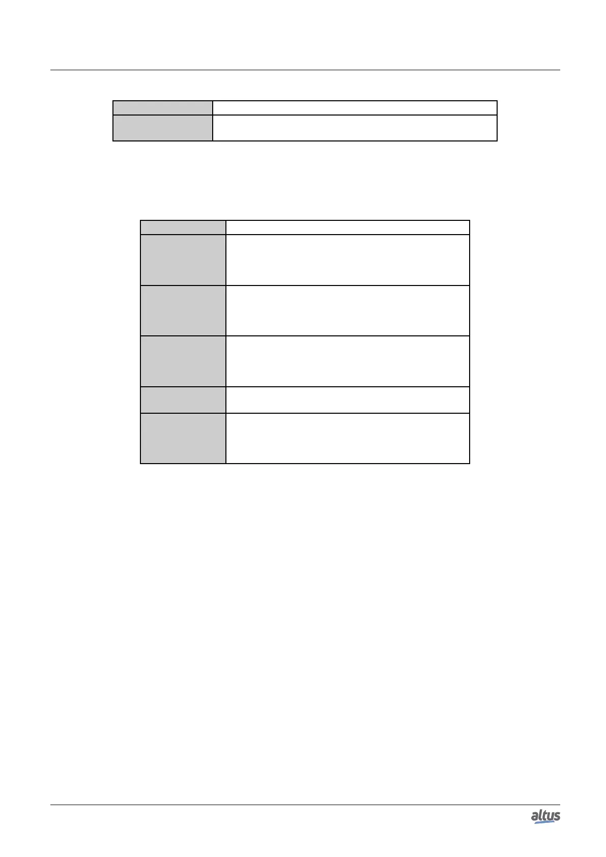
Interfaces Description
NET 1
RJ45 communication connector 10/100Base-TX stan-
dard. Allows the point to point or network communi-
cation. For further utilization information, see Ethernet
Interfaces Configuration section.
NET 2
RJ45 communication connector 10/100Base-TX stan-
dard. Allows the point to point or network. For further
utilization information, see Ethernet Interfaces Configu-
ration section.
COM 1
DB9 female connector for RS-232 communication stan-
dard. Allows the point to point or network. For further
utilization information, see Serial Interfaces Configura-
tion section.
COM 2
For further utilization information, see Serial Interfaces
Configuration section.
MEMORY
SLOT
Memory card slot. Allows the use of a memory card for
different types of data storage such as: user logs, Web
pages, project documentation and files. For further uti-
lization information, see Memory Card section.
Table 4: Connection Interfaces
7

 Loading...