5. CONFIGURATION
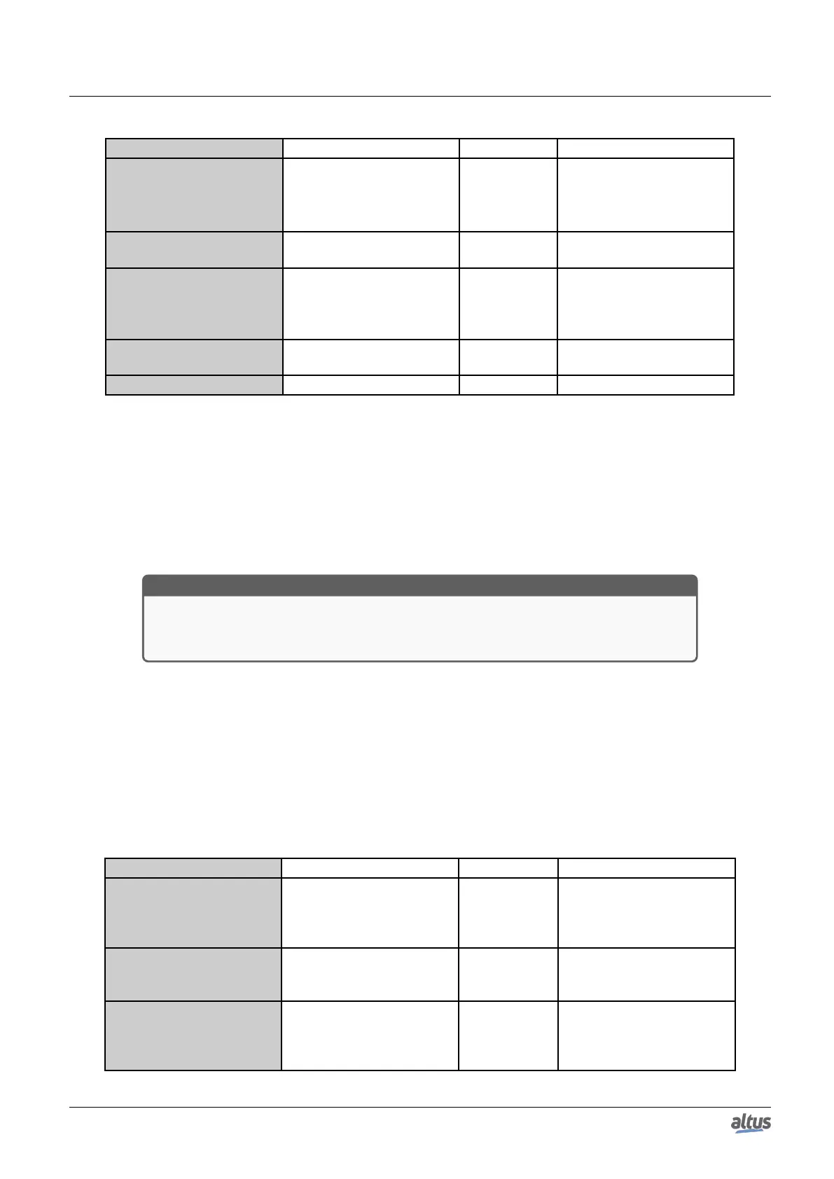
Configuration Description Default Options
Data Type MODBUS data type Coil
Coil (1 bit)
Holding Register (16 bits)
Input Status (1 bit)
Input Register (16 bits)
Data Start Address
MODBUS data initial ad-
dress
1 1 to 65536
Data Size MODBUS data quantity 8
1 to 65536 (Holding Regis-
ter and Input Register)
8 to 65536 (Coil and Input
Status)
IEC Variable
Variables initial address
(%Q)
- 0 to 2147483647
Read-only Allow reading only Disabled Enabled or Disabled
Table 124: Server Mappings
Notes:
Options: the values written in the column Options may vary according with the configured MODBUS data.
Data Size: the Data Size value sets the maximum amount of data that a MODBUS relation can access from the initial
address. Thus, to read a continuous range of addresses, it is necessary that all addresses are declared in a single relation. This
field varies according to the set MODBUS data type, that is, when selected Coil or Input Status, the field Data Size must be a
number multiple of 8. It is also important to take care so the maximum value is not greater than the addressable output memory
size and the attributed values aren’t the same already used during the application.
ATTENTION
When accessing the communication data memory is between devices with different endian-
ism (Little-Endian and Big-Endian), inversion of the read/write data may occur. In this case,
the user must adjust the data in the application.
IEC Variable: in case the MODBUS data type is Coil or Input Status (bit), the IEC variables initial address will be in the
format for example %QX10.1. However, if the MODBUS data type is Holding Register or Input Register (16 bits), the IEC
variables initial address will be in the format %QW. This field is limited by the memory size of the addressable output variables
(%Q) from each CPU, which can be seen on the Memory section.
Read-only: when enabled, it only allows the communication master to read the variable data. It does not allow the writing.
This option is valid for the writing functions only.
Default: the default cannot be defined for the IEC Variable field as the creation of a protocol instance can be made at any
moment within the application development, making the MasterTool IEC XE software allocate a value itself from the direct
representation output variables range (%Q) still not used. The default cannot be defined for the Data Size field as it will vary
according to selected MODBUS data type.
The settings present on the Filters... button, described in table below, are relative to the TCP communication filters:
Configuration Description Default Value Options
Write Filter IP Address
Specifies a range of IPs with
write access in the variables
declared in the MODBUS
interface.
0.0.0.0
0.0.0.0 to
255.255.255.255
Write Filter Mask
Specifies the subnet mask in
conjunction with the IP filter
parameter for writing.
0.0.0.0
0.0.0.0 to
255.255.255.255
Read Filter IP Address
Specifies a range of IPs with
read access in the variables
declared in the MODBUS
interface.
0.0.0.0
0.0.0.0 to
255.255.255.255
151

 Loading...