7. MAINTENANCE
Direct representation Size
AT Variable
DG_Module.tDetailed.*
Description
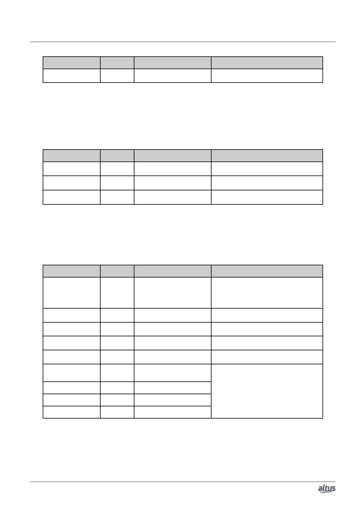
%QX(n+36).1
BIT
Reset.
bWatchdogReset
The CPU was restarted due the active watchdog
in the last startup.
Table 228: Reset Detailed Diagnostics Group Description
Note:
Brownout Reset: The brownout reset diagnostic is only true when the power supply exceed the minimum limit required
in its technical characteristics, remaining in low-voltage, i.e. without undergoing any interrupt. The CPU will identify the drop
in supply and will indicate the power failure diagnostic. When the voltage is reestablished, the CPU will automatically reset
and will indicate the brownout reset diagnostic.
Direct representation Size
AT Variable
DG_Module.tDetailed.*
Description
%QX(n+37).0
BIT
Thermometer.
bOverTemperatureAlarm
1
Alarm generated due internal temperature at 85
◦
C or above it.
%QX(n+37).1
BIT
Thermometer.
bUnderTemperatureAlarm
1
Alarm generated due internal temperature at 0
◦
C or under it.
%QD(n+38)
DINT
Thermometer.
diTemperature
1
Temperature read in the internal sensor of the
CPU.
Table 229: Thermometer Detailed Diagnostics Group Description
Note:
Temperature: In order to see the temperature directly in the memory address, a conversion must be made, since the data
size is DINT and monitoring is done in 4 bytes. Therefore, it’s recommended to use the associated symbolic variable, because
it already provides the final temperature value.
Direct representation Size
AT Variable
DG_Module.tDetailed.*
Description
%QB(n+42)
BYTE
Serial.COM1.
byProtocol
Protocol selected in the COM 1:
00: Without protocol
01: MODBUS RTU Master
02: MODBUS RTU Slave
03: Other protocol
%QD(n+43)
DWORD
Serial.COM1.
dwRXBytes
Counter of characters received from COM 1 (0
to 4294967295).
%QD(n+47)
DWORD
Serial.COM1.
dwTXBytes
Counter of characters transmitted from COM 1
(0 to 4294967295).
%QW(n+51)
WORD
Serial.COM1.
wRXPendingBytes
Number of characters left in the reading buffer
in COM 1 (0 to 65535).
%QW(n+53)
WORD
Serial.COM1.
wTXPendingBytes
Number of characters left in the transmission
buffer in COM 1 (0 to 65535).
%QW(n+55)
WORD
Serial.COM1.
wBreakErrorCounter
COM 1 error counters (0 to 65535). These
counters are restarted in the following condi-
tions:
%QW(n+57)
WORD
Serial.COM1.
wParityErrorCounter
Energizing
%QW(n+59)
WORD
Serial.COM1.
wFrameErrorCounter
Configuration of the COM 1 serial port
%QW(n+61)
WORD
Serial.COM1.
wRXOverrunCounter
Removal of RX and TX queues
Table 230: Serial COM 1 Detailed Diagnostics Group Description
Note:
Parity Error Counter: When the serial COM 1 is configured Without Parity, this error counter won’t be incremented
when it receives a message with a different parity. In this case, a frame error will be indicated.
363

 Loading...