CPU Specifications
and Operation
4–37
CPU Specifications and Operation
Many host software packages allow you to specify the MODBUS data type and the
MODBUS address that corresponds to the PLC memory location. This is the easiest
method, but not all packages allow you to do it this way.
The actual equation used to calculate the address depends on the type of PLC data
you are using. The PLC memory types are split into two categories for this purpose.
S Discrete – X, SP, Y, CR, S, T, C (contacts)
S Word – V, Timer current value, Counter current value
In either case, you basically convert the PLC octal address to decimal and add the
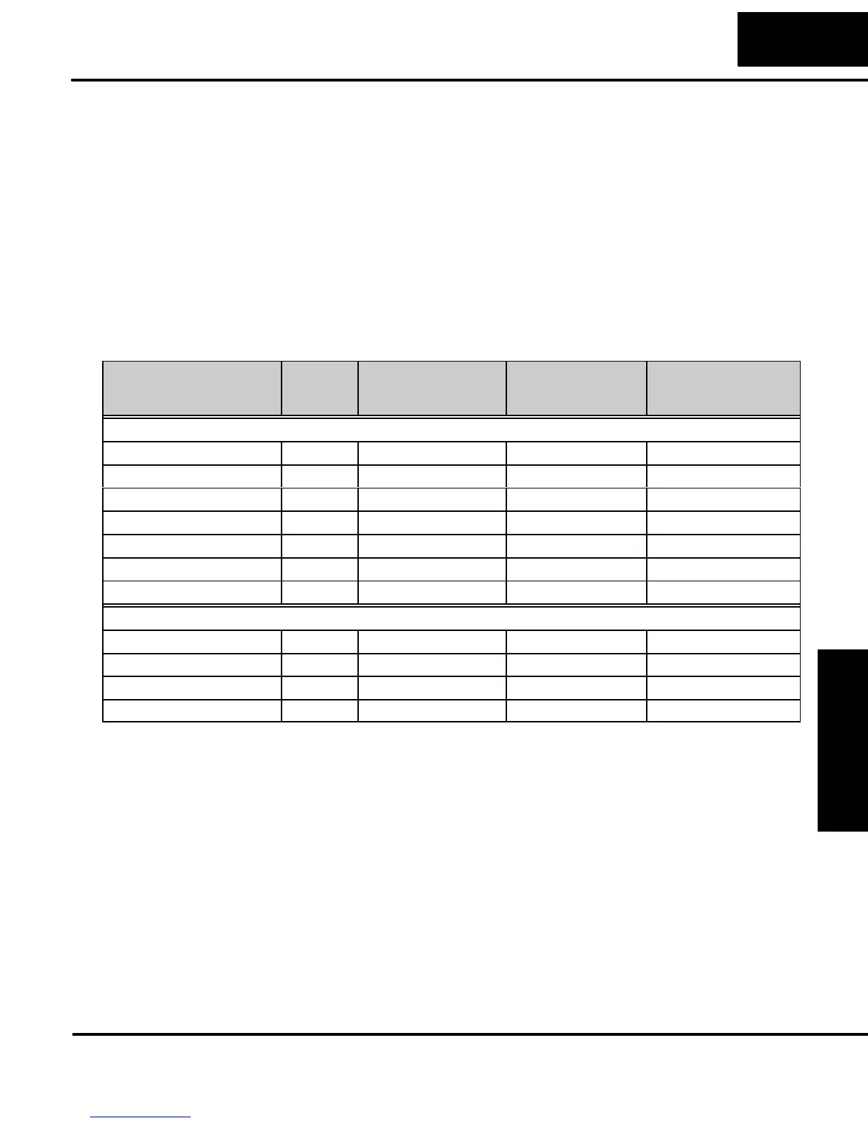
appropriate MODBUS address (if required). The table below shows the exact
equation used for each group of data.
DL05 Memory Type QTY
(Dec.)
PLC Range
(Octal)
MODBUS
Address Range
(Decimal)
MODBUS
Data Type
For Discrete Data Types .... Convert PLC Addr. to Dec. + Start of Range + Data Type
Inputs (X) 256 X0 – X377 2048 – 2303 Input
Special Relays (SP) 512 SP0 – SP777 3072 – 3583 Input
Outputs (Y) 256 Y0 – Y377 2048 – 2303 Coil
Control Relays (CR) 512 C0 – C777 3072 – 4583 Coil
Timer Contacts (T) 128 T0 – T177 6144 – 6271 Coil
Counter Contacts (CT) 128 CT0 – CT177 6400 – 6527 Coil
Stage Status Bits (S) 256 S0 – S377 5120 – 5375 Coil
For Word Data Types .... Convert PLC Addr. to Dec. + Data Type
Timer Current Values (V) 128 V0 – V177 0 – 127 Input Register
Counter Current Values (V) 128 V1000 – V1177 512 – 639 Input Register
V Memory, user data (V) 3968 V1200 – V7377 640 – 3839 Holding Register
V Memory, non-volatile (V) 128 V7600 – V7777 3968 – 4095 Holding Register
If Your Host Software
Requires the Data
Type and Address...