PID Loop Operation
Maintenance
and Troubleshooting
8–54
PID Loop Operation
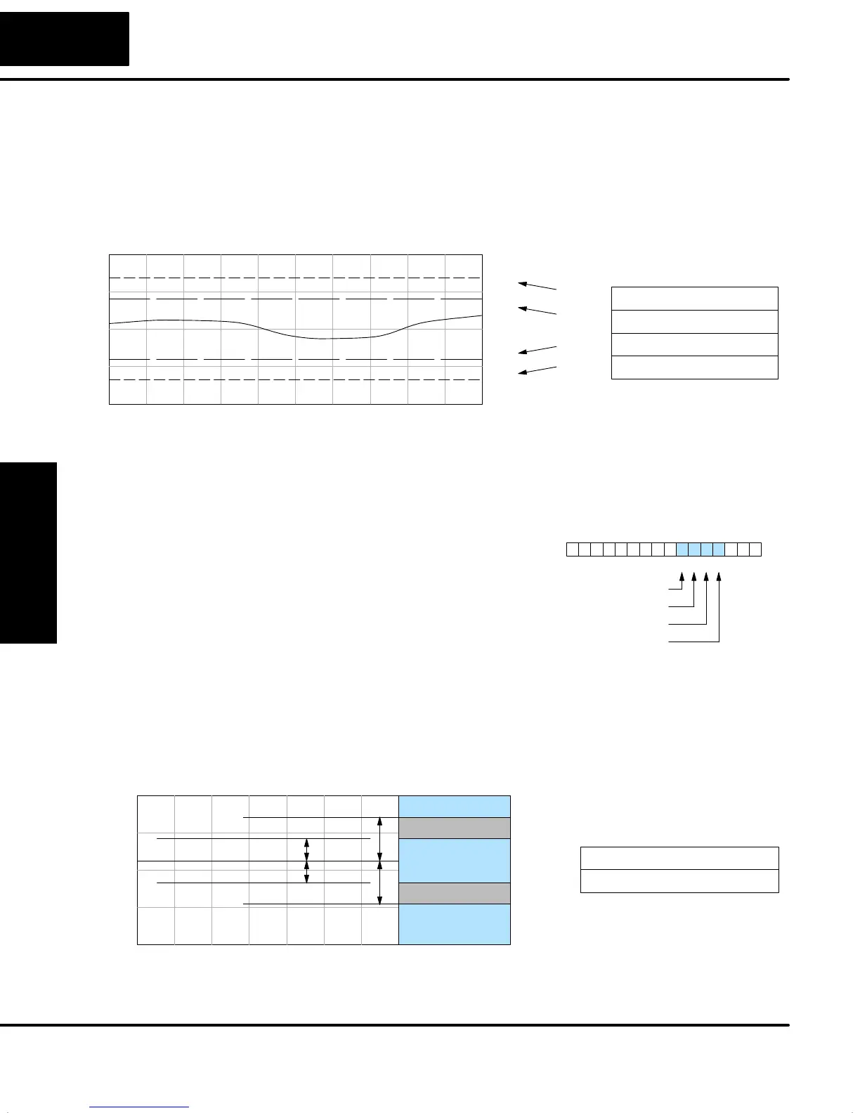
The PV absolute value alarms are organized as two upper and two lower alarms.
The alarm status is false as long as the PV value remains in the region between the
upper and lower alarms, as shown below. The alarms nearest the safe zone are
named High Alarm and Low Alarm. If the loop loses control, the PV will cross one of
these thresholds first. Therefore, you can program the appropriate alarm threshold
values in the loop table locations shown below to the right. The data format is the
same as the PV and SP (12-bit or 15-bit). The threshold values for these alarms
should be set to give an operator an early warning if the process loses control.
PV
High–high Alarm
High Alarm
Low Alarm
Low–low Alarm
Loop Table
V+16 High-high AlarmXXXX
V+15 High AlarmXXXX
V+14 Low AlarmXXXX
V+13 Low-low AlarmXXXX
If the process remains out of control for some time, the PV will eventually cross one
of the outer alarm thresholds, named High-high alarm and Low-low alarm. Their
threshold values are programmed using the loop table registers listed above. A
High-high or Low-low alarm indicates a serious condition exists, and needs the
immediate attention of the operator.
The PV Absolute Value Alarms are
reported in the four bits in the PID Mode
and Alarm Status word in the loop table, as
shown to the right. We highly recommend
using ladder logic to monitor these bits.
The bit-of-word instructions make this
easy to do. Additionally, you can monitor
PID alarms using DirectSOFT.
PID Mode and Alarm Status V+06
013456789101112131415 2Bit
High-high Alarm
High Alarm
Low Alarm
Low-low Alarm
The PV Deviation Alarms monitor the PV deviation with respect to the SP value. The
deviation alarm has two programmable thresholds, and each threshold is applied
equally above and below the current SP value. In the figure below, the smaller
deviation alarm is called the “Yellow Deviation”, indicating a cautionary condition for
the loop. The larger deviation alarm is called the “Red Deviation”, indicating a strong
error condition for the loop. The threshold values use the loop parameter table
locations V+17 and V+20 as shown.
SP
Red Deviation Alarm
Yellow Deviation Alarm
Loop Table
V+17 Yellow Deviation AlarmXXXX
V+20 Red Deviation AlarmXXXX
Yellow Deviation Alarm
Red Deviation Alarm
Green
Yellow
Red
Yellow
Red
The thresholds define zones, which fluctuate with the SP value. The green zone
which surrounds the SP value represents a safe (no alarm) condition. The yellow
zones lie outside the green zone, and the red zones are beyond those.
PV Absolute
Value Alarms
PV Deviation
Alarms