High-Speed Input and
Pulse Output Features
3–50
High-speed Input and Pulse Output Features
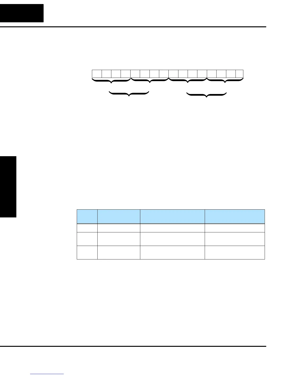
Recall that V7633 is the HSIO Mode Select register. Refer to the diagram below. Use
BCD 50 in the lower byte of V7633 to select the High-Speed Counter Mode. The
DL05 does not use bits 8 - 15 in V7633.
015 14 13 12
Memory Location V7633
11 10 123456789Bits
00000010100
HSIO Mode Setup (BCD)
0000
50 = Pulse Catch Input
00 05
0
Bits 8 - 15 are not used
in V7633.
Choose the most convenient method of programming V7633 from the following:
S Include load and out instructions in your ladder program
S DirectSOFT’s memory editor
S Use the Handheld Programmer D2–HPP
We recommend using the first method above so that the HSIO setup becomes an
integral part of your application program. An example program later in this section
shows how to do this.
The configurable discrete input options for Pulse Catch Mode are listed in the table
below. Input X0 is the pulse input, and must have “0005” loaded into it configuration
register V7634. Inputs X1 and X2 can only be filtered inputs. Each input has its own
configuration register and filter time constant.
Input Configuration
Register
Function Hex Code
Required
X0 V7634 Pulse Catch Input 0005
X1 V7635 Filtered Input xx06 (xx = filter time)
0 - 99 ms (BCD)
X2 V7636 Filtered Input xx06 (xx = filter time)
0 - 99 ms (BCD)
Setup for Mode 50
X Input
Configuration