Getting Started
1–9
Getting Started
Step 5: Switch on the System Power
Apply power to the system and ensure the PWR indicator on the DL05 is on. If not,
remove power from the system and check all wiring and refer to the troubleshooting
section in Chapter 9 for assistance.
Step 6: Initialize Scratchpad Memory
It’s a good precaution to always clear the system memory (scratchpad memory) on a
new DL05. There are two ways to clear the system memory:
S In DirectSOFT, select the PLC menu, then Setup, then Initialize
Scratchpad. For additional information, see the DirectSOFT Manual.
S For the Handheld Programmer, use the AUX key and execute AUX 54.
See the Handheld Programmer Manual for additional information.
Step 7: Enter a Ladder Program
At this point, DirectSOFT programmers need to refer to the Quick Start Tutorial in
the DirectSOFT Manual. There you will learn how to establish a communications link
with the DL05 PLC, change CPU modes to Run or Program, and enter a program.
If you are learning how to program with the Handheld Programmer, make sure the
CPU is in Program Mode (the RUN LED on the front of the DL05 should be off). If the
RUN LED is on, use the MODE key on the Handheld Programmer to put the PLC in
Program Mode. Enter the following keystrokes on the Handheld Programmer.
ENT CLR
3
D
TMR
N
4
E
SHFT
CLR CLR
2
C
4
E
AUX ENT
NEXT
STR
$
0
A
ENT
OUT
GX
0
A
ENT
ENT
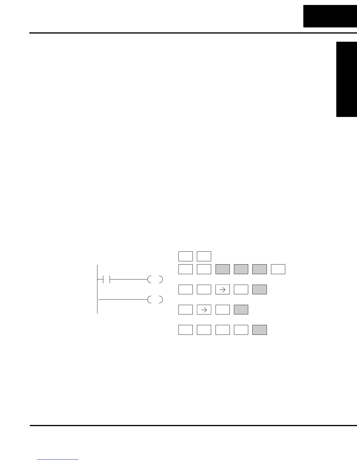
Clear the Program
Move to the first
address and enter
X0 contact
Enter output Y0
Enter the END
statement
END
X0
OUT
Y0
Equivalent DirectSOFT display
After entering the simple example program put the PLC in Run mode by using the
Mode key on the Handheld Programmer.
The RUN indicator on the PLC will illuminate indicating the CPU has entered the Run
mode. If not, repeat this step, ensuring the program is entered properly or refer to the
troubleshooting guide in chapter 8.
After the CPU enters the run mode, the output status indicator for Y0 should follow
the switch status on input channel X0. When the switch is on, the output will be on.