PID Loop Operation
Maintenance
8–21
PID Loop Operation
The DL05 gives you the three standard control modes: Manual, Automatic, and
Cascade. The sources of the three basic variables SP, PV, and control output are
different for each mode. An introduction to the three control modes and their signal
sources follows.
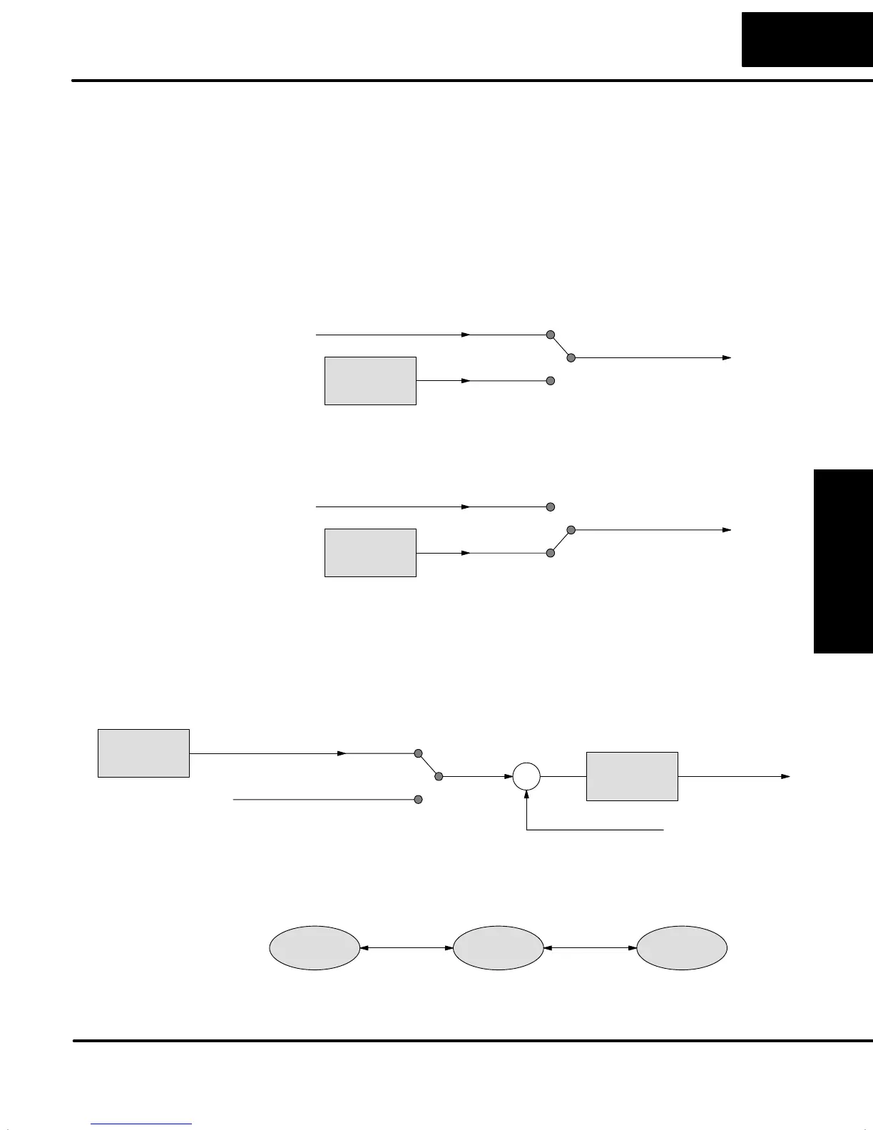
In Manual Mode, the loop is not executing PID calculations (however, loop alarms
are still active). With regard to the loop table, the CPU stops writing values to location
V+05 for that loop. It is expected that an operator or other intelligent source is
manually controlling the output, by observing the PV and writing data to V+05 as
necessary to keep the process under control. The drawing below shows the
equivalent schematic diagram of manual mode operation.
Loop
Calculation
Control Output V+05
Input from Operator
Manual
Auto
In Automatic Mode, the loop operates normally and generates new control output
values. It calculates the PID equation and writes the result in location V+05 every
sample period of that loop. The equivalent schematic diagram is shown below.
Loop
Calculation
Control Output V+05
Input from Operator
Manual
Auto
In Cascade Mode, the loop operates as it does in Automatic Mode, with one
important difference. The data source for the SP changes from its normal location at
V+02, using the control output value from another loop. So in Auto or Manual modes,
the loop calculation uses the data at V+02. In Cascade Mode, the loop calculation
reads the control output from another loop’s parameter table.
Process Variable
S
+
–
Setpoint
Cascade
Auto/Manual
Control Output V+05
Normal SP V+02
Loop
Calculation
Control Output
Loop
Calculation
Cascaded loopAnother loop
As pictured below, A loop can be changed from one mode to another, but cannot go
from Manual Mode directly to Cascade, or vice versa. This mode change is
prohibited because a loop would be changing two data sources at the same time,
and could cause a loss of control.
Manual Automatic Cascade
Loop Modes