RLL PLUS
Stage Programming
7–19
RLL
PLUS
Stage Programming
Parallel Processing Concepts
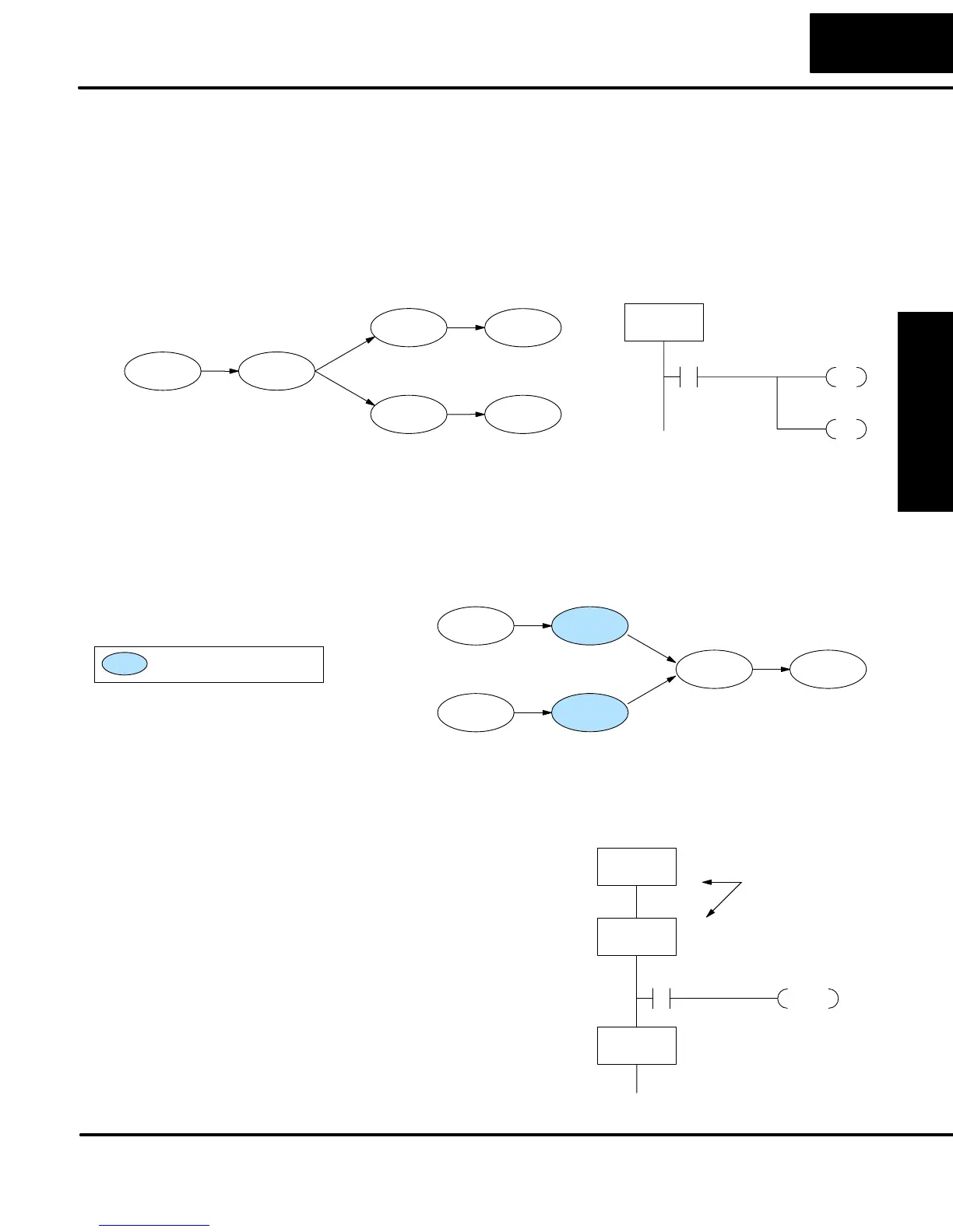
Previously in this chapter we discussed how a state may transition to either one state
or another, called an exclusive transition. In other cases, we may need to branch
simultaneously to two or more parallel processes, as shown below. It is acceptable
to use all JMP instructions as shown, or we could use one JMP and a Set Stage bit
instruction(s) (at least one must be a JMP, in order to leave S1). Remember that all
instructions in a stage execute, even when it transitions (the JMP is not a GOTO).
S1S0
S2
S4
S3
S5
S2
JMP
SG
S1
X0
Push–On State
S4
JMP
X0
Process A
Process B
Note that if we want Stages S2 and S4 to energize exactly on the same scan, both
stages must be located below or above Stage S1 in the ladder program (see the
explanation at the bottom of page 7–7). Overall, parallel branching is easy!
Now we consider the opposite case of parallel branching, which is converging
processes. This simply means we stop doing multiple things and continue doing one
thing at a time. In the figure below, processes A and B converge when stages S2 and
S4 transition to S5 at some point in time. So, S2 and S4 are Convergence Stages.
S5
S1
S3
S2
S4
S6
= Convergence Stage
Process A
Process B
While the converging principle is simple enough, it brings a new complication. As
parallel processing completes, the multiple processes almost never finish at the
same time. In other words, how can we know whether Stage S2 or S4 will finish last?
This is an important point, because we have to decide how to transition to Stage S5.
The solution is to coordinate the transition
condition out of convergence stages. We
accomplish this with a stage type
designed for this purpose: the
Convergence Stage (type CV). In the
example to the right, convergence stages
S2 and S4 are required to be grouped
together as shown. No logic is permitted
between CV stages! The transition
condition (X3 in this case) must be located
in the last convergence stage. The
transition condition only has power flow
when all convergence stages in the group
are active.
CVJMP
S5
X3
CV
S2
CV
S4
Convergence
Stages
SG
S5
Parallel Processes
Converging
Processes
Convergence
Stages
(CV)