Installation, Wiring,
and Specifications
2–12
Installation, Wiring, and Specifications
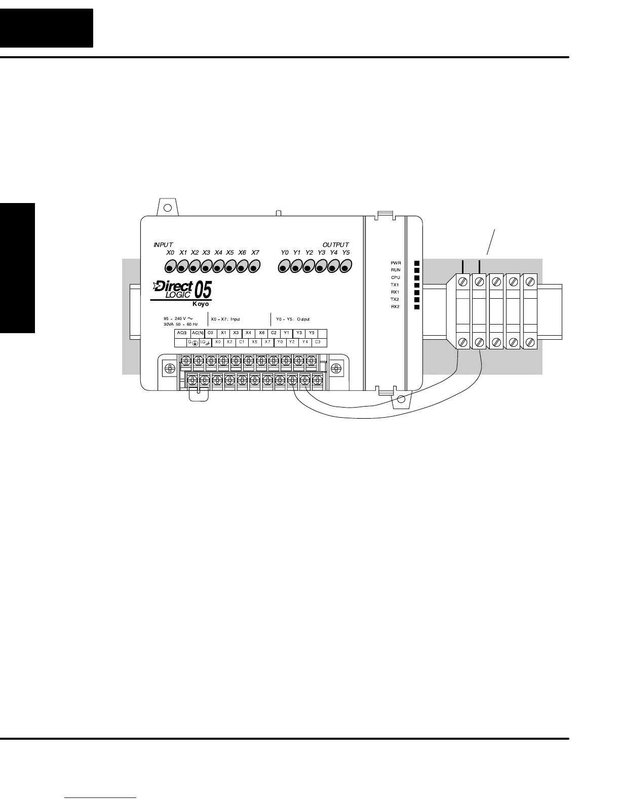
Input and Output circuits on DL05 Micro PLCs do not have internal fuses. In order to
protect your Micro PLC, we suggest you add external fuses to your I/O wiring. A
fast-blow fuse, with a lower current rating than the I/O bank’s common current rating
can be wired to each common. Or, a fuse with a rating of slightly less than the
maximum current per output point can be added to each output. Refer to the Micro
PLC specification sheets further in this chapter to find the maximum current per
output point or per output common. Adding the external fuse does not guarantee the
prevention of Micro PLC damage, but it will provide added protection.
External Fuses
(shown with DIN Rail, Fuse Blocks)
All DL05 Micro PLCs have a fixed I/O configuration. It follows the same octal
numbering system used on other DirectLogic family PLCs, starting at X0 and Y0. The
letter X is always used to indicate inputs and the letter Y is always used for outputs.
The I/O numbering always starts at zero and does not include the digits 8 or 9. The
addresses are typically assigned in groups of 8 or 16, depending on the number of
points in an I/O group. For the DL05 the eight inputs use reference numbers X0 – X7.
The six output points use references Y0 – Y5.
Fuse Protection
for Input and
Output Circuits
I/O Point
Numbering