RLL PLUS
Stage Programming
7–4
RLL
PLUS
Stage Programming
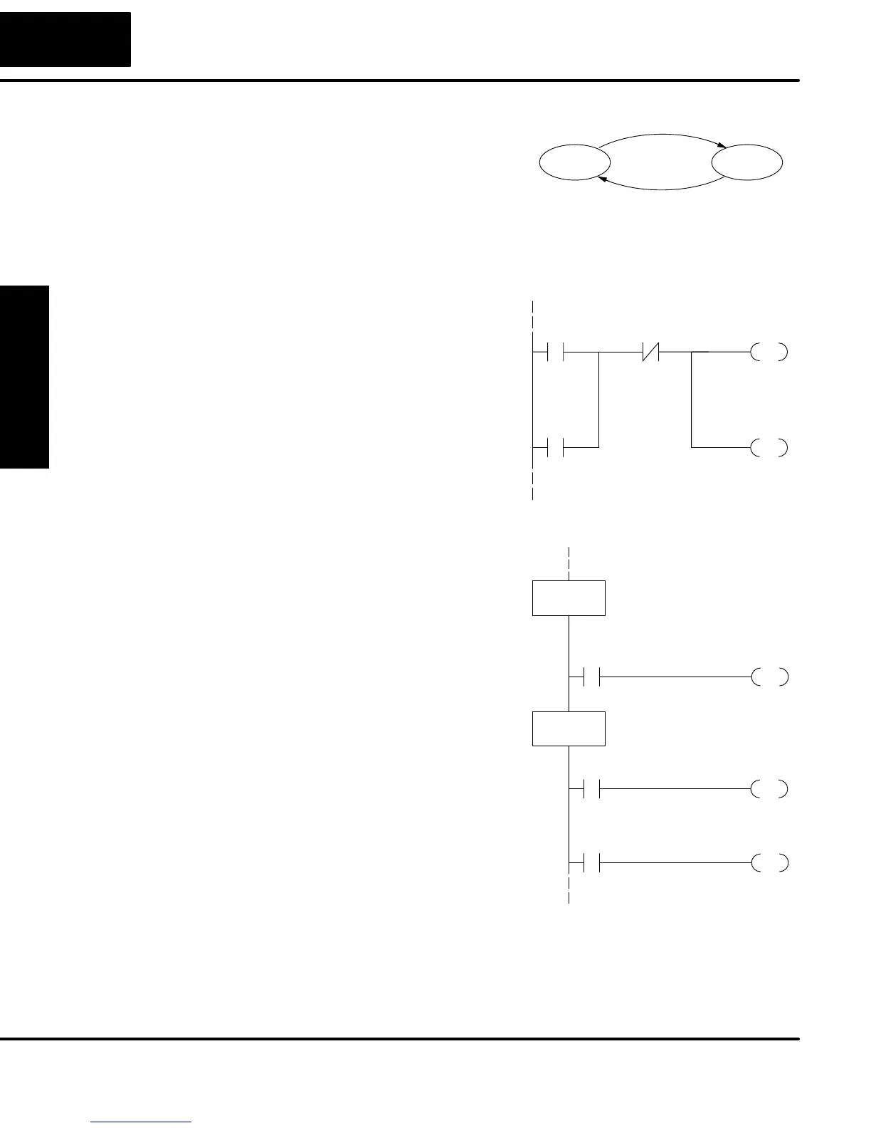
The state transition diagram to the right is
a picture of the solution we need to create.
The beauty of it is this: it expresses the
problem independently of the
programming language we may use to
realize it. In other words, by drawing the
diagram we have already solved the
control problem!
OFF ON
X0
X1
Output equation: Y0 = ON
First, we’ll translate the state diagram to traditional RLL. Then we’ll show how easy it
is to translate the diagram into a stage programming solution.
The RLL solution is shown to the right. It
consists of a self-latching control relay,
C0. When the On pushbutton (X0) is
pressed, output coil C0 turns on and the
C0 contact on the second row latches
itself on. So, X0 sets the latch C0 on, and
it remains on after the X0 contact opens.
The motor output Y0 also has power flow,
so the motor is now on.
When the Off pushbutton (X1) is pressed,
it opens the normally-closed X1 contact,
which resets the latch. Motor output Y0
turns off when the latch coil C0 goes off.
X1X0
OUT
C0
OUT
Y0
C0
Set
Reset Latch
Output
Latch
The stage program solution is shown to
the right. The two inline stage boxes S0
and S1 correspond to the two states OFF
and ON. The ladder rung(s) below each
stage box belong to each respective
stage. This means that the PLC only has
to scan those rungs when the
corresponding stage is active!
For now, let’s assume we begin in the OFF
State, so stage S0 is active. When the On
pushbutton (X0) is pressed, a stage
transition occurs. The JMP S1 instruction
executes, which simply turns off the Stage
bit S0 and turns on Stage bit S1. So on the
next PLC scan, the CPU will not execute
Stage S0, but will execute stage S1!
In the On State (Stage S1), we want the
motor to always be on. The special relay
contact SP1 is defined as always on, so Y0
turns the motor on.
S1
X0
JMP
SG
S0
S0
X1
JMP
SG
S1
OUT
Y0
OFF State
ON State
Output
Transition
Transition
SP1
Always on
When the Off pushbutton (X1) is pressed, a transition back to the Off State occurs.
The JMP S0 instruction executes, which simply turns off the Stage bit S1 and turns
on Stage bit S0. On the next PLC scan, the CPU will not execute Stage S1, so the
motor output Y0 will turn off. The Off state (Stage 0) will be ready for the next cycle.
RLL Equivalent
Stage Equivalent