PID Loop Operation
Maintenance
8–61
PID Loop Operation
The normal state for the ramp/soak control bits is all zeros. Ladder logic must set
only one control bit at a time.
S Start – a 0-to-1 transition will start the ramp soak profile. The CPU must
be in Run Mode, and the loop can be in Manual or Auto Mode. If the
profile is not interrupted by a Hold or Jog command, it finishes normally.
S Hold – a 0-to-1 transition will stop the ramp/soak profile in its current
state, and the SP value will be frozen.
S Resume – a 0-to-1 transition cause the ramp/soak generator to resume
operation if it is in the hold state. The SP values will resume from their
previous value.
S Jog – a 0-to-1 transition will cause the ramp/soak generator to truncate
the current segment (step), and go to the next segment.
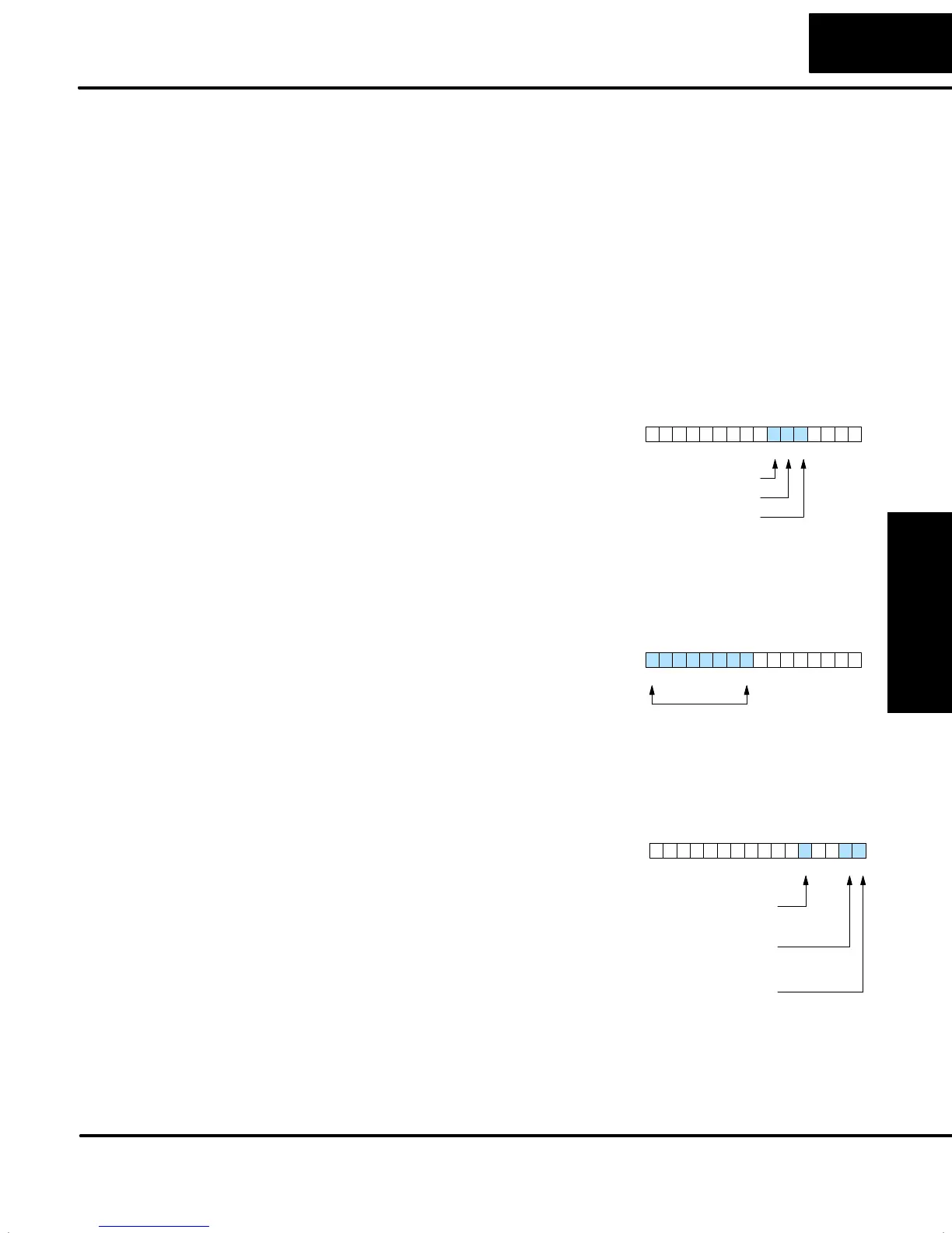
You can monitor the Ramp/Soak profile
status using other bits in the Ramp/Soak
Settings V+33 word, shown to the right.
S R/S Profile Complete – =1 when the
last programmed step is done.
S Soak PV Deviation – =1 when the
error (SP–PV) exceeds the specified
deviation in the R/S table.
S R/S Profile in Hold – =1 when the
profile was active but is now in hold.
Ramp/Soak Settings V+33
013456789101112131415 2Bit
R/S Profile Complete
Soak PV Deviation
R/S Profile in Hold
The number of the current step is available
in the upper 8 bits of the Ramp/Soak
Settings V+33 word. The bits represent a
2-digit hex number, ranging from 1 to 10.
Ladder logic can monitor these to
synchronize other parts of the program
with the ramp/soak profile. Load this word
to the accumulator and shift right 8 bits,
and you have the step number.
Ramp/Soak Settings V+33
013456789101112131415 2Bit
Current Profile Step, 2–digit hex
Value = 01 to 10 hex,
or 1 to 16 decimal
The starting address for the ramp/soak
table must be a valid location. If the
address points outside the range of user
V-memory, one of the bits to the right will
turn on when the ramp/soak generator is
started. We recommend using
DirectSOFT32 to configure the
ramp/soak table. It automatically range
checks the addresses for you.
Ramp/Soak Table Error V+35
013456789101112131415 2Bit
Starting Address set out of
V-memory upper range
Starting Address set out
of V-memory lower range
Starting Address set in
reserved system V-memory
It’s a good idea to test your ramp/soak profile before using it to control the process.
This is easy to do, because the ramp/soak generator will run even when the loop is in
Manual Mode. Using DirectSOFT32’s PID View will be a real time-saver, because it
will draw the profile on-screen for you. Be sure to set the trending timebase slow
enough to display completed ramp-soak segment pairs in the waveform window.
Ramp/Soak Profile
Monitoring
Ramp/Soak
Programming
Errors
Testing Your
Ramp/Soak Profile