Standard
RLL Instructions
5–32
Standard RLL Instructions
Timer, Counter, and Shift Register Instructions
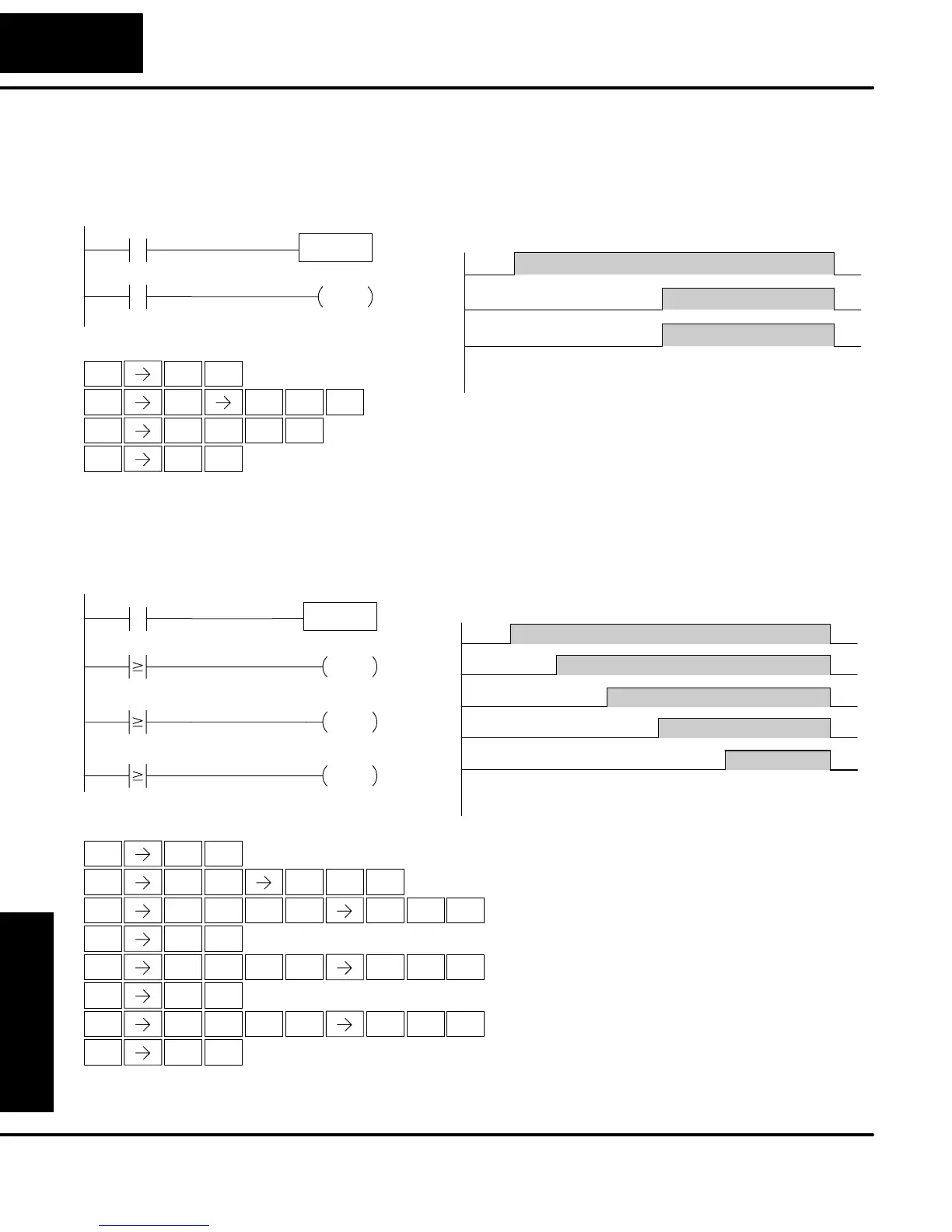
In the following example, a single input timer is used with a preset of 3 seconds. The
timer discrete status bit (T2) will turn on when the timer has timed for 3 seconds. The
timer is reset when X1 turns off, turning the discrete status bit off and resetting the
timer current value to 0.
STR
$
TMR
N
2
C
STR
$
SHFT
MLR
T
2
C
ENT
OUT
GX
Handheld Programmer Keystrokes
X1
TMR T2
K30
T2
Y0
OUT
X1
T2
123456 780
01020304050 600
Current
Value
Y0
Timing Diagram
DirectSOFT
1/10 Seconds
Seconds
1
B
ENT
3
D
0
A
ENT
ENT
0
A
In the following example, a single input timer is used with a preset of 4.5 seconds.
Comparative contacts are used to energize Y3, Y4, and Y5 at one second intervals
respectively. When X1 is turned off the timer will be reset to 0 and the comparative
contacts will turn off Y3, Y4, and Y5.
1
B
ENT
andheld Programmer Keystrokes
X1
TMR T20
K45
TA20 K10
TA20 K20
TA20 K30
Y4
OUT
Y3
OUT
Y5
OUT
X1
Y3
123456780
01020304050 600
Current
Value
Y4
Y5
T2
1/10 Seconds
Seconds
STR
$
TMR
N
2
C
ENT
0
A
4
E
5
F
STR
$
SHFT
MLR
T
2
C
0
A
1
B
ENT
OUT
GX
ENT
3
D
STR
$
SHFT
MLR
T
2
C
0
A
ENT
OUT
GX
ENT
2
C
4
E
STR
$
SHFT
MLR
T
2
C
0
A
ENT
OUT
GX
ENT
3
D
5
F
0
A
0
A
0
A
Timer Example
Using Discrete
Status Bits
Timer Example
Using Comparative
Contacts