Installation, Wiring
Installation and
Safety Guidelines
and Specifications
2–50
Installation, Wiring, and Specifications
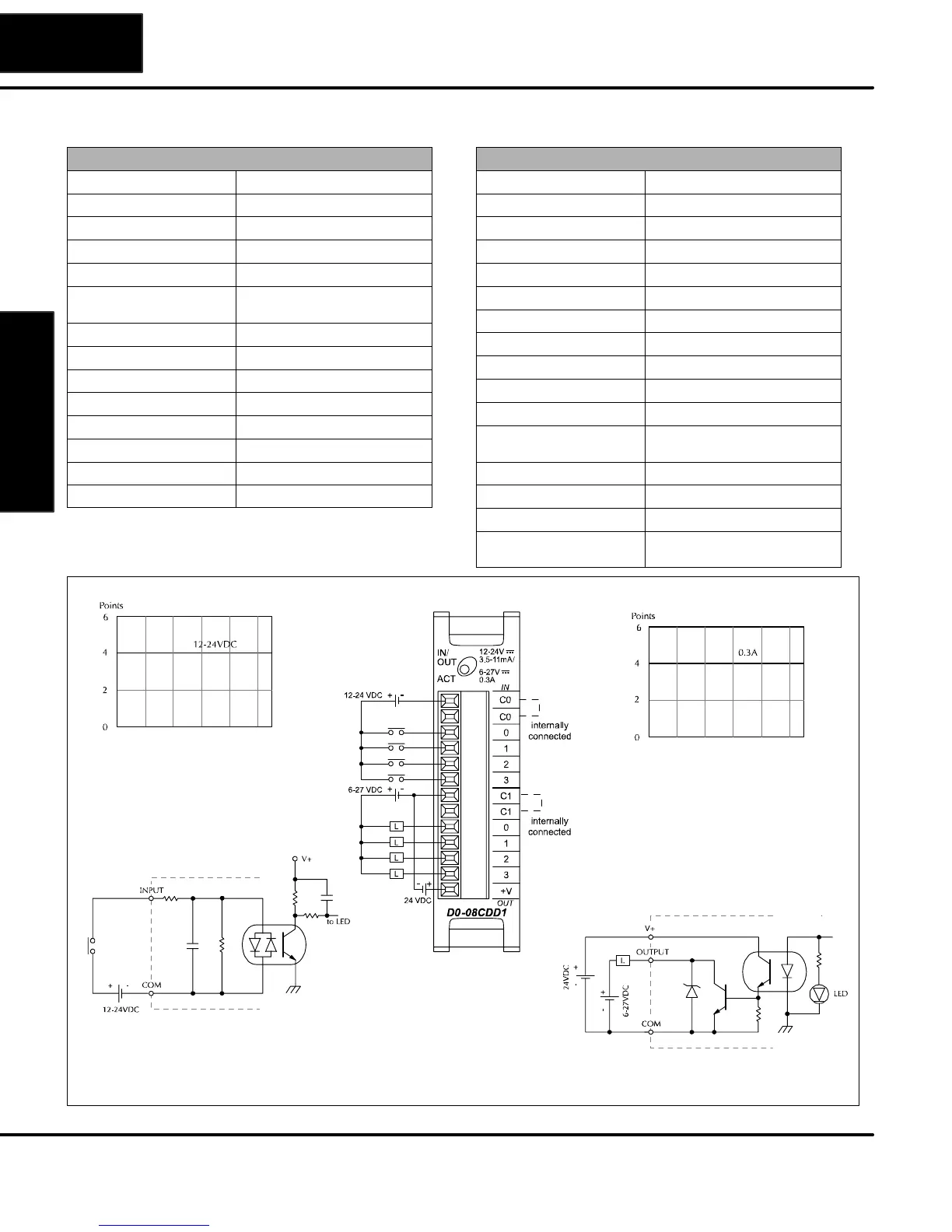
D0–08CDD1 DC Input and Output
Input Specification
Inputs per module 4 (sink/source)
Operating voltage range 10.8–26.4 VDC
Input voltage range 12–24 VDC
Peak voltage 30.0 VDC
Maximum input current 11 mA @ 26.4 VDC
Input current Typical: 4 mA @ 12 VDC
8.5 mA @ 24 VDC
Input impedance 2.8k @ 12–24 VDC
ON voltage level > 10.0 VDC
OFF voltage level < 2.0 VDC
Minimum ON current 3.5 mA
Maximum OFF current 0.5 mA
ON to OFF response 2–8 ms, typical 4 ms
OFF to ON response 2–8 ms, typical 4 ms
Commons 2 non–isolated (4 pts./common)
Output Specification
Outputs per module 4 (sinking)
Operating voltage range 6–27 VDC
Output voltage range 5–30 VDC
Peak voltage 50.0 VDC
Maximum output current 0.3 A/point, 1.2 A/common
Minimum output current 0.5 mA
Maximum leakage current 1.5 A @ 30.0 VDC
ON voltage drop 0.5 VDC @ 0.3 A
Maximum inrush current 1 A for 10 ms
OFF to ON response < 10 s
ON to OFF response < 60 s
Status indicators Module activity:
one green LED
Commons 2 non–isolated (4 pts./common)
Fuse N/A
Base power required (5 V) Max. 200 mA (all points ON)
External DC power required
(24V)
20–28 VDC, maximum 80 mA
(all pts. ON)
Output Derating Chart
Input Derating Chart
Equivalent output circuit
Equivalent input circuit
0
10 20 30 40 50 55
Ambient Temperature (°C/°F)
32
50 68 86 104 122 131
C°
F°
0
10 20 30 40 50 55
Ambient Temperature (°C/°F)
32
50 68 86 104 122 131
C°
F°
Configuration shown is for current sinking
Note: The DL05 must have firmware version V4.10 (or later) for this module to function properly.