High-Speed Input and
Pulse Output Features
3–45
High-Speed Input and Pulse Output Features
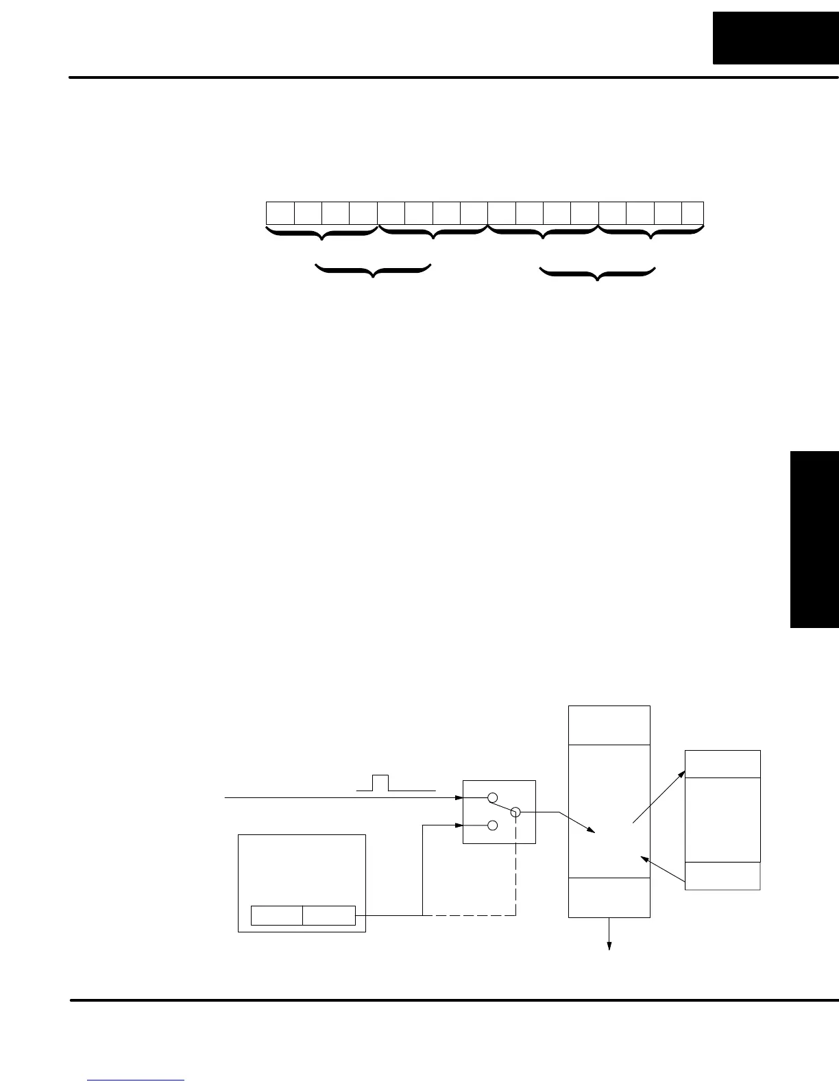
Recall that V7633 is the HSIO Mode Select register. Refer to the diagram below. Use
BCD 40 in the lower byte of V7633 to select the High-Speed Counter Mode. The
DL05 does not use bits 8 - 15 in V7633.
015 14 13 12
Memory Location V7633
11 10 123456789Bits
00000000100
HSIO Mode Setup (BCD)
0000
40 = High-Speed Interrupt
00 04
0
Bits 8 - 15 are not used
in V7633.
Choose the most convenient method of programming V7633 from the following:
S Include load and out instructions in your ladder program
S DirectSOFT’s memory editor
S Use the Handheld Programmer D2–HPP
We recommend using the first method above so that the HSIO setup becomes an
integral part of your application program. An example program later in this section
shows how to do this.
Refer to the drawing below. The source of the interrupt may be external (X0), or the
HSIO timer function. The setup parameter in V7634 serves a dual purpose:,
S It selects between the two interrupt sources, external (X0) or an internal
timer.
S In the case of the timer interrupt, it programs the interrupt timebase
between 5 and 999 mS.
The resulting interrupt uses label INT 0 in the ladder program. Be sure to include the
Enable Interrupt (ENI) instruction at the beginning of your program. Otherwise, the
interrupt routine will not be executed.
X0, External Interrupt
CPU Scan
Interrupt source /
Time select
V7634
xxx4
Input
Update
Ladder
Program
Execution
Input
Update
current
instruction
INT
Interrupt
Routine
Program
IRT
TIMER
Setup for Mode 40
Interrupts and the
Ladder Program