High-Speed Input and
Pulse Output Features
3–4
High-speed Input and Pulse Output Features
Choosing the HSIO Operating Mode
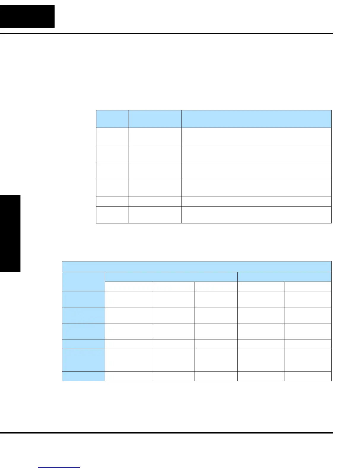
The High-Speed I/O circuit operates in one of 6 basic modes as listed in the table
below. The number in the left column is the mode number (later, we’ll use these
numbers to configure the PLC). Choose one of the following modes according to the
primary function you want from the dedicated High-Speed I/O circuit. You can simply
use all eight inputs and six outputs as regular I/O points with Mode 60.
Mode
Number
Mode Name Mode Features
10 High-Speed
Counter
5 kHz counter with 24 presets and reset input,
counts up only, causes interrupt on preset
20 Quadrature
Counter
Channel A / Channel B 5 kHz quadrature input,
counts up and down
30 Pulse Output Stepper control – pulse and direction signals,
programmable motion profile (7kHz max.)
40 High-Speed
Interrupt
Generates an interrupt based on input transition
or time
50 Pulse Catch Captures narrow pulses on a selected input
60 Discrete/Filtered
Input
Rejects narrow pulses on selected inputs
In choosing one of the six high-speed I/O modes, the I/O points listed in the table
below operate only as the function listed. If an input point is not specifically used to
support a particular mode, it usually operates as a filtered input by default. Similarly,
output points operate normally unless Pulse Output mode is selected.
Physical I/O Point Usage
DC Input Points DC Output Points
Mode X0 X1 X2 Y0 Y1
High-Speed
Counter
Counter clock Filtered Input Filtered Input
or Reset Cnt
Regular Output Regular Output
Quadrature
Counter
Phase A Input Phase B Input Filtered Input
or Reset Cnt
Regular Output Regular Output
High-Speed
Interrupt
Interrupt Input Filtered Input Filtered Input Regular Output Regular Output
Pulse Catch Pulse Input Filtered Input Filtered Input Regular Output Regular Output
Pulse Output Filtered Input Filtered Input Filtered Input, Pulse
or
CW Pulse
Direction
or
CCW Pulse
Filtered Input Filtered Input Filtered Input Filtered Input Regular Output Regular Output
Mode 60 (Filtered Inputs) is the default mode. The DL05 is initialized to this mode at
the factory, and any time you reset V-memory scratchpad. In the default condition,
X0–X2 are filtered inputs (10 mS delay) and Y0–Y1 are standard outputs.
Understanding the
Six Modes
Default Mode