RLL PLUS
Stage Programming
7–11
RLL
PLUS
Stage Programming
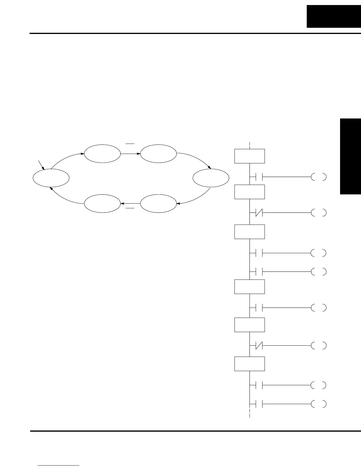
Now we are ready to draw the state transition diagram. Like the previous light bulb
controller example, this application also has just one switch for the command input.
Refer to the figure below.
S When the door is down (DOWN state), nothing happens until X0
energizes. Its push and release brings us to the RAISE state, where
output Y1 turns on and causes the motor to raise the door.
S We transition to the UP state when the up limit switch (X1) energizes,
and turns off the motor.
S Then nothing happens until another X0 press-release cycle occurs. That
takes us to the LOWER state, turning on output Y2 to command the
motor to lower the door. We transition back to the DOWN state when the
down limit switch (X2) energizes.
The equivalent stage program is shown to the
right. For now, we will assume the door is
down at powerup, so the desired powerup
state is DOWN. We make S0 an initial stage
(ISG). Stage S0 remains active until the door
control pushbutton activates. Then we
transition (JMP) to Push-UP stage, S1.
A push-release cycle of the pushbutton takes
us through stage S1 to the RAISE stage, S2.
We use the always-on contact SP1 to
energize the motor’s raise command, Y1.
When the door reaches the fully-raised
position, the up limit switch X1 activates. This
takes us to the UP Stage S3, where we wait
until another door control command occurs.
In the UP Stage S3, a push-release cycle of
the pushbutton will take us to the LOWER
Stage S5, where we activate Y2 to command
the motor to lower the door. This continues
until the door reaches the down limit switch,
X2. When X2 closes, we transition from Stage
S5 to the DOWN stage S0, where we began.
NOTE: The only special thing about an initial
stage (ISG) is that it is automatically active at
powerup. Afterwards, it is just like any other.
S1
X0
JMP
ISG
S0
S2
JMP
SG
S1
OUT
Y1
DOWN State
SP1
S3
X1
JMP
SG
S2
SG
S3
X0
S4
JMP
X0
Push–UP State
RAISE State
UP State
X0
Push–UP
UP
Push–DOWN
DOWN
X0
LOWER
RAISE
X0
X1
X0
X2
Output equations: Y2 = LOWERY1 = RAISE
S5
JMP
SG
S4
X0
Push–DOWN State
OUT
Y2
SP1
S0
X2
JMP
SG
S5
LOWER State
Powerup
Draw the State
Diagram