Installation, Wiring,
and Specifications
2–7
Installation, Wiring, and Specifications
There are many things to consider when designing the panel layout. The following items
correspond to the diagram shown. Note: there may be additional requirements,
depending on your application and use of other components in the cabinet.
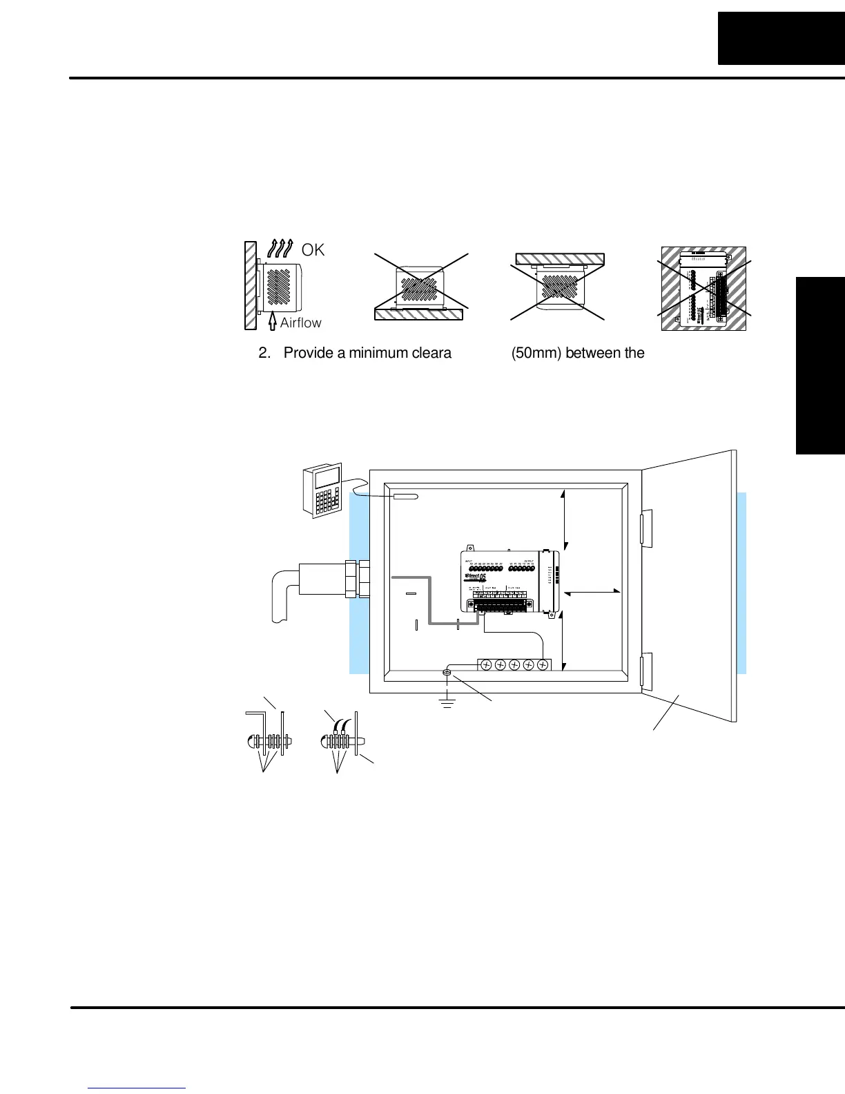
1. Mount the PLCs horizontally as shown below to provide proper ventilation.
You cannot mount the DL05 units vertically, upside down, or on a flat
horizontal surface. If you place more than one unit in a cabinet, there must
be a minimum of 7.2” (183mm) between the units.
ÍÍÍÍÍ
ÍÍÍÍÍ
ÍÍÍÍÍ
ÍÍÍÍÍ
ÍÍÍÍÍ
OK
Airflow
2. Provide a minimum clearance of 2” (50mm) between the unit and all sides of
the cabinet. Note, remember to allow for any operator panels or other items
mounted in the door.
3. There should also be at least 3” (78mm) of clearance between the unit and
any wiring ducts that run parallel to the terminals.
Earth Ground
Panel Ground
Terminal
DL05
Power
Source
Temperature
Probe
Star Washers
Panel Ground Braid
Copper Lugs
Panel or
Single Point
Ground
Star Washers
BUS Bar
À
Note: there is a minimum of 2” (30mm)
clearance between the panel door
or any devices mounted in the panel door
2"
50mm
min.
Æ
2"
50mm
min.
Ä
Å
and the nearest DL05 component.
2"
50mm
min.
Ç
Not to Scale
Micro PLC
Á
Á
Á
Á
4. The ground terminal on the DL05 base must be connected to a single point
ground. Use copper stranded wire to achieve a low impedance. Copper
eye lugs should be crimped and soldered to the ends of the stranded wire to
ensure good surface contact.
5. There must be a single point ground (i.e. copper bus bar) for all devices in
the panel requiring an earth ground return. The single point of ground must
be connected to the panel ground termination. The panel ground
termination must be connected to earth ground. Minimum wire sizes, color
coding, and general safety practices should comply with appropriate
electrical codes and standards for your area.
Panel Layout &
Clearances