PID Loop Operation
Maintenance
and Troubleshooting
8–30
PID Loop Operation
The Error term is internal to the CPUs PID loop controller, and is generated again in
each PID calculation. Although its data is not directly accessible, you can easily
calculate it by subtracting: Error = (SP–PV). If the PV square-root extract is enabled,
then Error = (SP – (sqrt(PV)). In any case, the size of the error and algebraic sign
determine the next change of the control output for each PID calculation.
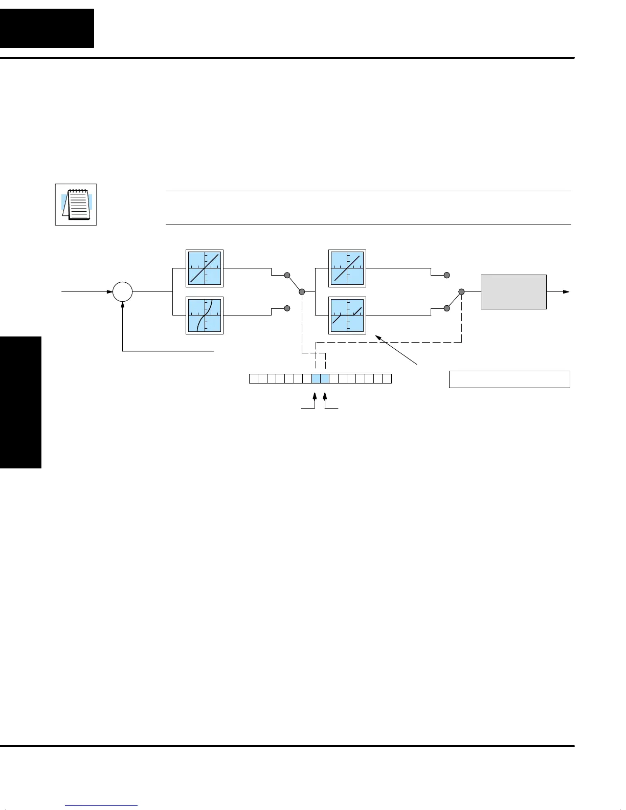
Now we will superimpose some “special effects” on to the error term as described.
Refer to the diagram below. Bit 7 of the PID Mode Setting 1 V+00 word lets you select
a linear or squared error term, and bit 8 enables or disables the error deadband.
NOTE: When first configuring a loop, it’s best to use the standard error term. After
the loop is tuned, then you will be able to tell if these functions will enhance control.
Process Variable
Loop
Calculation
S
Error
Term
+
–
Setpoint
PID Mode 1 Setting V+00
013456789101112131415 2Bit
Linear/Squared Error select
0
1
Error
Error
squared
0
1
Error
Error with
Deadband
Error Deadband select
Loop Table
V+23 Error DeadbandXXXX
Error Squared – When selected, the squared error function simply squares the
error term (but preserves the original algebraic sign), which is used in the
calculation. This affects the Control Output by diminishing its response to smaller
error values, but maintaining its response to larger errors. Some situations in which
the error squared term might be useful:
S Noisy PV signal – using a squared error term can reduce the effect of
low-frequency electrical noise on the PV, which will make the control
system jittery. A squared error maintains the response to larger errors.
S Non-linear process – some processes (such as chemical pH control)
require non-linear controllers for best results. Another application is
surge tank control, where the Control Output signal must be smooth.
Error Deadband – When selected, the error deadband function takes a range of
small error values near zero, and simply substitutes zero as the value of the error. If
the error is larger than the deadband range, then the error value is used normally.
Loop parameter location V+23 must be programmed with a desired deadband
amount. Units are the same as the SP and PV units (0 to FFF in 12-bit mode, and 0 to
7FFF in 15-bit mode). The PID loop controller automatically applies the deadband
symmetrically about the zero-error point.
Error Term
Configuration