Standard
RLL Instructions
5–101
Standard RLL Instructions
Program Control Instructions
K aaa
The Master Line Set instruction allows the
program to control sections of ladder logic
by forming a new power rail controlled by
the main left power rail. The main left rail is
always master line 0. When a MLS K1
instruction is used, a new power rail is
created at level 1. Master Line Sets and
Master Line Resets can be used to nest
power rails up to seven levels deep.
MLS
Operand Data Type DL05 Range
aaa
Constant K 1–7
K aaa
The Master Line Reset instruction marks
the end of control for the corresponding
MLS instruction. The MLR reference is one
less than the corresponding MLS.
MLR
Operand Data Type DL05 Range
aaa
Constant K 0–7
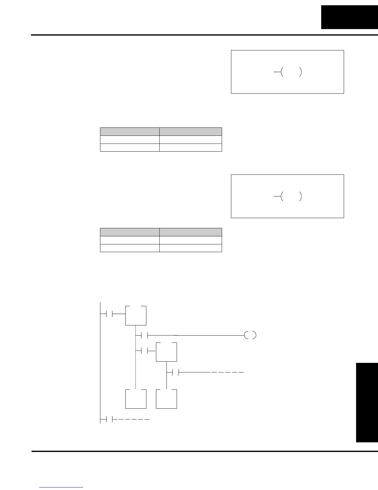
The Master Line Set (MLS) and Master Line Reset (MLR) instructions allow you to
quickly enable (or disable) sections of the RLL program. This provides program
control flexibility. The following example shows how the MLS and MLR instructions
operate by creating a sub power rail for control logic.
X0
X1
X2
OUT
Y7
X3
MLS
MLR
MLS
MLR
When contact X0 is on, logic under the first MLS
will be executed.
When contact X2 and X0 is on, logic
under the second MLS will be
executed.
The MLR instructions note the end of the Master Control area. (They will be entered in
adjacent addresses.)
X10
K1
K2
K0 K1
Master Line Set
(MLS)
Master Line Reset
(MLR)
Understanding
Master Control
Relays