PID Loop Operation
Maintenance
and Troubleshooting
8–28
PID Loop Operation
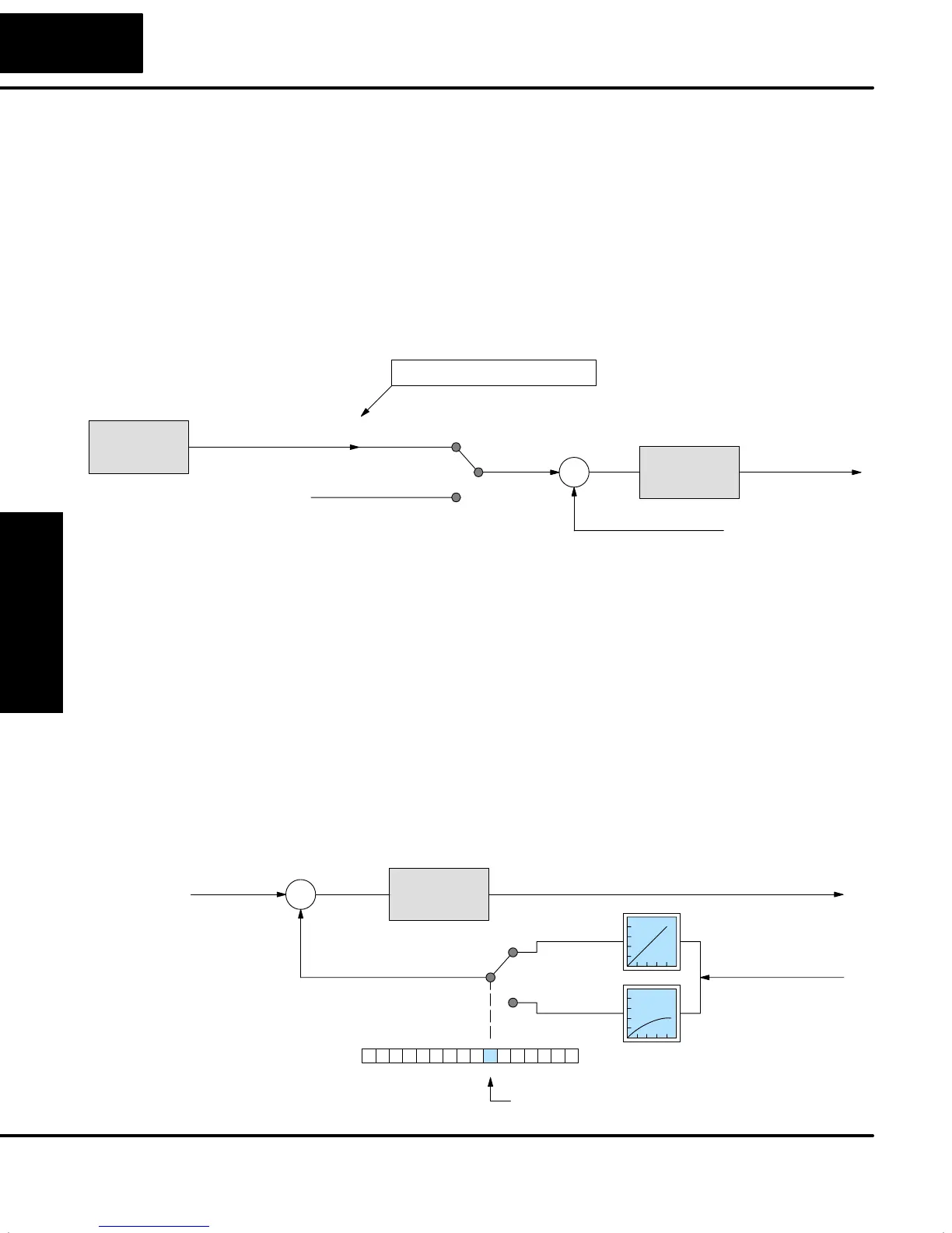
You may recall there are generally several possible data sources for the SP value.
The PID loop controller has the built-in ability to select between two sources
according to the current loop mode. Refer to the figure below. A loop reads its
setpoint from table location V+02 in Auto or Manual modes. If you plan to use
Cascade Mode for the loop at any time, then you must program its loop parameter
table with a remote setpoint pointer.
The Remote SP pointer resides in location V+32 in the loop table. For loops that will
be cascaded (made a minor loop), you will need to program this location with the
address of the major loop’s Control Output address. Find the starting location of the
major loop’s parameter table and add offset +05 to it.
Process Variable
S
+
–
Setpoint
Cascade
Auto/Manual
Control Output V+05
Normal SP V+02
Loop
Calculation
Control Output
Loop
Calculation
Cascaded loop
Another loop
Loop Table
V+32 Remote SP PointerXXXX
(minor loop)
(major loop)
A DirectSOFT32 Loop Setup dialog box will allow you to enter the Remote SP
pointer if you know the address. Otherwise, you can enter it with a HPP or program it
through ladder logic using the LDA instruction.
The process variable input to each loop is the value the loop is ultimately trying to
control, to make it equal to the setpoint and follow setpoint changes as quickly as
possible. Most sensors for process variables have a primarily linear response curve.
Most temperature sensors are mostly linear across their sensing range. However,
flow sensing using an orifice plate technique gives a signal representing
(approximately) the square of the flow. Therefore, a square-root extract function is
necessary before using the signal in a linear control system (such as PID).
Some flow transducers are available which will do the square-root extract, but they
add cost to the sensor package. The PID loop PV input has a selectable square-root
extract function, pictured below. You can select between normal (linear) PV data,
and data needing a square-root extract by using PID Mode setting V+00 word, bit 6.
Loop
Calculation
S
+
–
Control Output
PID Mode 1 Setting V+00
013456789101112131415 2Bit
Linear/Square-root PV select
0
1
Linear PV
Square-
root PV
Setpoint
Process Variable
Remote Setpoint
(SP) Location
Process Variable
(PV) Configuration