High-Speed Input and
Pulse Output Features
3–5
High-Speed Input and Pulse Output Features
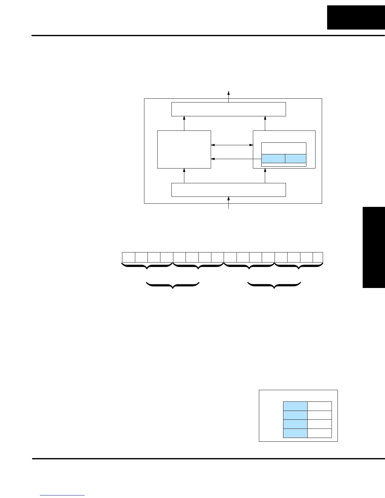
If you have chosen a mode suited to the high-speed I/O needs of your application,
we’re ready to proceed to configure the PLC to operate accordingly. In the block
diagram below, notice the V-memory detail in the expanded CPU block. V-memory
location V7633 determines the functional mode of the high-speed I/O circuit. This is
the most important V-memory configuration value for HSIO functions!
Output Circuit
Input Circuit
CPU
PLC
DL05
HighĆSpeed
I/O Circuit
X0 - X2
Y0, Y1
X3- X7
Y2 - Y5
VĆmemory
V7633
xxxx
Mode Select
I/O data
The contents of V7633 is a 16-bit word, to be entered in binary–coded decimal. The
figure below defines what each 4-bit BCD digit of the word represents.
015 14 13 12
Memory Location V7633
11 10 123456789Bits
00000010100
HSIO Mode Setup (BCD)
0000
00 = Not Used
10 = High-Speed Counting Mode
20 = Quadrature Counting Mode
30 = Pulse Output Train
0
40 = High-Speed Interrupts
50 = Pulse Catching
60 = Discrete Filtered Inputs (default)
5
0
00
Bits 8 - 15 are not used
in V7633.
Bits 0 – 7 define the mode number 00, 10.. 60 previously referenced in this chapter.
The example data “2050” shown selects Mode 50 – Pulse Catch (BCD = 50). The
DL05 PLC ignores bits 8 - 15 in V7633.
In addition to configuring V7633 for the
HSIO mode, you’ll need to program the
next three locations in certain modes
according to the desired function of input
points X0 – X2. Other memory locations
may require configuring, depending on the
HSIO mode (see the corresponding
section for particular HSIO modes).
VĆmemory
V7633 xxxx
Mode
V7634 xxxxX0
V7635 xxxxX1
V7636 xxxxX2
Configuring the
HSIO Mode
Configuring
Inputs X0 – X2