High-Speed Input and
Pulse Output Features
3–28
High-speed Input and Pulse Output Features
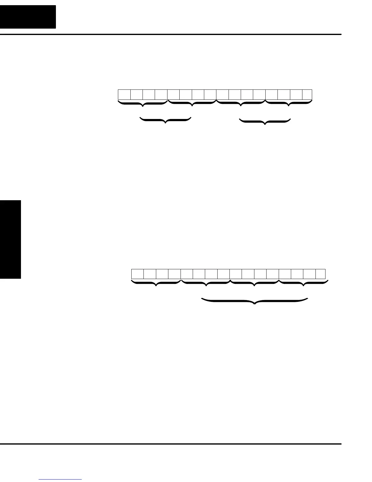
Recall that V7633 is the HSIO Mode Select register. Refer to the diagram below. Use
BCD 30 in the lower byte of V7633 to select the High-Speed Counter Mode. The
DL05 does not use bits 8 - 15 in V7633.
015 14 13 12
Memory Location V7633
11 10 123456789Bits
00000011000
HSIO Mode Setup (BCD)
0000
30 = Pulse Output
00 03
0
Bits 8 - 15 are not used
in V7633.
Choose the most convenient method of programming V7633 from the following:
S Include load and out instructions in your ladder program
S DirectSOFT’s memory editor
S Use the Handheld Programmer D2–HPP
We recommend using the first method above so that the HSIO setup becomes an
integral part of your application program. An example program later in this section
shows how to do this.
The first location in the Profile Parameter Table stores two key pieces of information.
The upper four bits (12–15) select the type of profile required. The lower 12 bits
(0–11) select the Target Velocity.
015 14 13 12
Memory Location V2320 (default)
11 10 123456789Bits
00000000000
Target Velocity ValueProfile Select (BCD)
0111
0 = Trapezoidal Profile, Absolute Position
8 = Trapezoidal Profile, Relative Position
Range = 4 to 700, representing
40 Hz to 7 kHz pulse rate
07 00
0
9 = Registration Profile, Relative Position
2 = Velocity Profile
The ladder program must program this location before initiating any of the three
profiles. The LD and OUT instruction will write all 16 bits, so be sure to fully specify
the full four-digit BCD value for the Position / Velocity Select Register each time.
The absolute and relative selection determines how the HSIO circuit will interpret
your specified target position. Absolute position targets are referenced to zero.
Relative position targets are referenced to the current position (previous target
position). You may choose whichever reference method that is most convenient for
your application.
Setup for Mode 30
Profile / Velocity
Select Register